


STOW G-2.9R A.C. GENERATOR — OPERATION & PARTS MANUAL — REV. #1 (10/28/04) — PAGE 19
STOW G-2.9R — CONTROLS AND INDICATORS
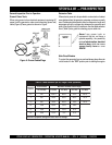
This
ROBIN
engine is equipped
with a low oil shutdown capability. A
built in sensor will automatically turn
off the engine should the oil level
fall below a safe operating condition.
Make sure the generator is placed
on level ground. Placing the generator on level ground will ensure
that the low oil sensor will function properly.
NOTE
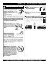
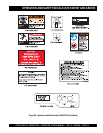
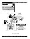
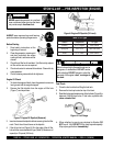
1. GFCI Ground – This ground connection point should be
connect to a good earth ground (ground rod). Applies to
units with S/N 5497956 and below.
2. GFCI Receptacle – This receptacle will provide 120V at
all times.
3. AC-Voltmeter – This voltmeter indicates (with a mark) the
rated 60 Hz, single phase output voltage. In addition the
voltmeter can also be used as a diagnostic tool. If the
voltmeter indicator (needle) is below the rated voltage,
engine problems may exist (low/high RPM's). To prevent
damage to the generator or power tools turn the generator
OFF and consult your authorized STOW service dealer.
4. Main Circuit Breaker – This single-pole 22 amp breaker
protects the generator from short circuiting or overloading.
When starting the generator
always
have the circuit breaker
placed in the "OFF" position.
5. Oil Alarm Indicator – This indicator will light in the event
of low oil.
6. Operation/ON-OFF Switches – For units with S/N
5497956 and below, place
rocker
switch in the "RUN"
position (up) for normal operation. To turn-off the generator
place switch in the "STOP" position (down). For units with
S/N 5497957 and above, place engine ON/OFF switch in
the "ON" position for normal operation.
To turn-off the
generator place switch in the "OFF" position.
7. 120V Output Receptacle – This NEMA L5-20R twist-
lock receptacle will provide 120V, 20 amps, 60 Hz.
Applies to units with S/N 5497957 and above.
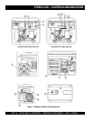
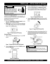
8. Generator Housing – Contains the rotor, rectifer field
coil assembly, aramature, bearings and other components
that make up generator asembly.
9. Spark Plug – Provides spark to the ignition system. Set
spark plug gap to 0.6 - 0.7 mm (0.024 - 0.028 inch). Clean
spark plug once a week.
10. Muffler/Heat Shield – Used to reduce noise and emissions.
NEVER touch this
heat shield
when the generator is in
use. Always allow time for the generator to cool down before
performing maintenance.
11. Oil Dipstick/ Filler Cap– Remove the filler cap dipstick
when checking the engine oil level. Add engine oil through
this filler port. See Table 4 for recommended type engine
oil.
12. Oil Drain Plug – Remove this plug to drain engine oil from
the crankcase.
13. Carburetor Fuel Cup – Inspect the fuel cup weekly for
water and dirt. Clean as referenced in the maintenance
section of this manual.
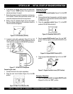
14. Choke Lever – Used for starting the engine.
Close
the
choke lever when starting a cold engine or in cold weather
conditions. The choke enriches the fuel mixture.
Open
the
choke lever if starting a warm engine or in warm weather
conditions.
15. Fuel Cock Lever – Turn this lever
downward
to
start
(down)the flow of fuel to the carburetor. Turn
upward
to
stop (
up
)
the flow of fuel.
16. Throttle Lever – Used to adjust engine RPM speed. This
unit is set at the factory and is not adjustable.
17. Recoil Starter (Pull Rope) – Used for manual-starting of
the engine. Pull the starter grip until resistance is felt, then
pull briskly and smoothly.
18. Engine – This generator uses a 5.1 HP ROBIN air-
cooled, 4-stroke , single cylinder, overhead camshaft
gasoline engine. Engine uses unleaded fuel.
19. Air Cleaner – Prevents dirt and other debris from entering
the fuel system. Remove wing-nut on top of air filter
cannister to gain access to filter element. NEVER run the
engine without an air cleaner.
20. Fuel Gauge – Read this gauge to determine when fuel is
low
.
21. Fuel Gauge/Tank – Remove this cap to add unleaded
gasoline to the fuel tank.
Replenish
with
clean unleaded
gasoline. Make sure cap is tightened securely. DO NOT
over fill. Fuel tank capacity is 3.17 gallons (12 liters).
22. Lifting Bail Eye – Attach a rope or chain to this lifting eye
when lifting of the generator is required. Never stand
underneath the generator while it is being lifted. Place lifting
eye in down position when not in use.
Applies to units
with S/N 5497957 and above.
ALWAYS allow time for the generator to
cool
down
before performing maintenance.
WARNINGWARNING
WARNINGWARNING
WARNING