


27
ENGLISH
EN
1.5 During operation
WARNING! The rotating tool is hot.
Pay attention to the safety distance specified in the
safety regulations.
Only start the motor when your feet are a safe dis-
tance from the rotating tool.
Always make sure you have a safe footing, espe-
cially on slopes. Never run, always walk slowly.
Never use the machine on steep slopes.
Hold the cable away from the rotating tool when
you are operating the machine.
Always move the machine sideways along the
slope, never up and down.
Switch off the machine when tilting or transport-
ing.
Never use the machine in the absence of protective
equipment or a protective cover.
Before lifting or moving the machine, switch off
the motor and wait until the rotating tool has come
to a complete standstill.
Before removing the grassbox or adjusting the op-
erating height, switch off the motor and wait until
the rotating tool has come to a complete standstill.
Replace worn or damaged blades as a complete set.
See the installation instructions. Always use genu-
ine spare parts. Cleaning and maintenance of the
machine may only be performed when the ma-
chine’s power supply is completely switched off.
Never store the machine in damp environments or
close to an open flame.
If the machine has run over a hard foreign object,
it must be examined by a specialist for safety rea-
sons (see list of dealers).
If the connection cable has been damaged during
use, it must immediately be disconnected from the
power supply. Do not touch the cable until the
power has been disconnected.
2 GENERAL
This symbol indicates WARNING. Per-
sonal injury and/or damage to property
may result if the instructions are not
followed carefully.
Before commencing installation, care-
fully read these instructions and safety
instructions.
2.1 References
The figures in these instructions for use are num-
bered 1, 2, 3, etc.
Components shown in the figures are marked A, B,
C, etc.
A reference to component C in figure 2 is written
“2:C”.
3 ASSEMBLY
To avoid injuries and damage to prop-
erty, do not use the machine until all the
measures in these instructions have
been carried out.
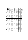
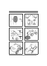
3.1 Wheels
Install the four wheels on the wheel axles in accor-
dance with fig. 1. Use the components below:
• Wheel 1:C.
• Locking washer 1:B.
• Wheel cap 1:A.
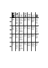
Install the rear wheel axle on the underside of the
machine in accordance with fig. 2. The angled
ends of the axle must fit into the slots in the side of
the machine. Use the components below:
• 2 locking loops 2:E (the smaller size).
• 4 screws with washers 2:F.
Install the front wheel axle on the underside of the
machine in accordance with fig. 2. The axle’s
height adjustment lever must fit into its locking de-
vice on the right side of the machine. Use the com-
ponents below:
• 2 locking loops 2:G (the larger size).
• 4 screws with washers 2:F.
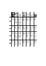
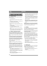
3.2 Handle
3.2.1 The handle’s lower section
1. Install the cable holder 3:K on the handle’s low-
er section.
2. Press the handle’s lower section down into the
machine.
3. Lock the handle into position with the two
screws 3:L.
3.2.2 The handle’s upper section
Install the handle’s upper section into its lower sec-
tion in accordance with fig. 3. Use the two screws
3:I and the wing nuts 3:J.
3.3 Start control
Install the start control on the handle’s upper sec-
tion in accordance with fig. 3. Use the two screws
3:H.
Secure the cable to the handle with the three
clamps 3:M.
3.4 Collector
Open the hatch and install the collector. Insert the
collector’s hooks into the slots in the upper part of
the opening. See fig. 4.