


8
ENGLISH
GB
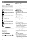
SYMBOLS
The following symbols are displayed on the ma-
chine in order to remind you about the safety pre-
cautions and attention necessary when using the
machine.
The symbols mean:
Warning! Read the Instruction Book and
Safety Manual before using the machine.
Warning! Keep spectators away. Beware of
objects being flung out.
Warning! Before starting any repair work,
disconnect the plug from the wall socket.
Warning! Keep the extension cord away
from the cutting deck.
Warning! Do not put hands or feet under the
cover of the machine when it is running.
Warning! The blades continue to rotate
even after the machine has been switched
off.
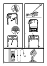
ASSEMBLING
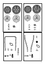
PARTS TO ASSEMBLE
Wheel type I (fig. 1)
Wheel type II (fig. 2)
Steering type I (fig. 3)
Steering type II (fig. 4)
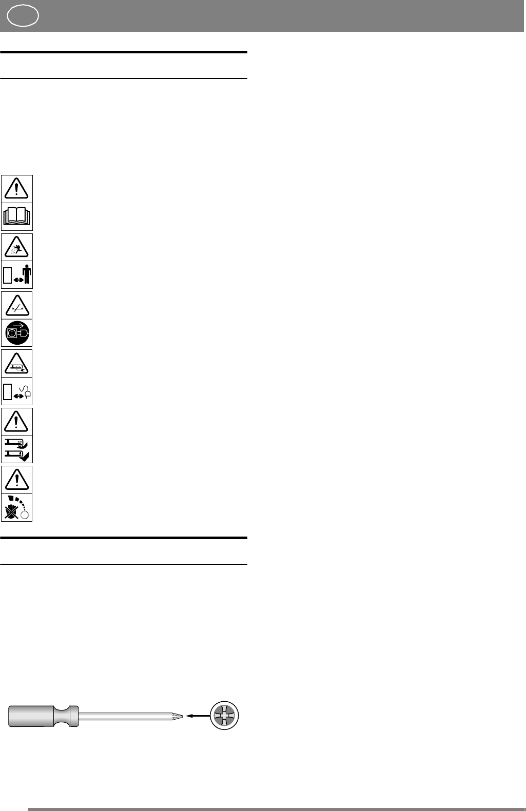
TOOLS FOR ASSEMBLEY
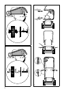
WHEELS type I (fig. 5)
1. Fit the bearings F in the wheel.
2. Apply the parts B, (F) and A on the wheel bolt.
3. Snap-on the centre cup C.
4. Fasten the wheel on the mower.
5. Tighten securely by hand using the finger-grip
holes in the hub cap.
WHEELS type II (fig. 6)
1. Fit the bearings F in the wheel.
2. Apply the parts B, G, E, (F) and A on the wheel
bolt.
3. Snap-on the centre cup C.
4. Fasten the wheel on the mower.
5. Tighten securely by hand using the finger-grip
holes in the hub cap.
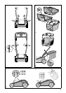
STEERING type I (fig. 7)
1 . Insert the tubes into the ends of the handlebar.
2. Fit the screws. Tighten securely.
3. Insert the ends of the U tube into the holes in the
chassis.
4. Fit the screws. Tighten securely.
5. Attach the handle to the U tube using the bolts,
washers and locking knobs provided. The han-
dlebar can be folded forwards by undoing the
locking knobs slightly. This reduces the space
the mower takes up during transport, etc.
6. Secure the electrical cable into the cable holder.
7. Fix the electrical cable using a cable tie.
STEERING type II (fig. 8)
1. Press the plugs into the steering sockets. Ensure
that the plugs are inserted in the correct end.
2. Press the steering sockets into the holes in the
chassis.
3. Fit the screws. Tighten securely.
4. Attach the handlebar to the steering sockets us-
ing screws, washers and locking knobs. The
handlebar can be tilted forward by loosening
the locking knobs slightly. The mower will then
take up less space during transportation.
5. Fix the electrical cable using a cable tie.
STOP