


ENGLISH
GB
8. Install the height setting strut (8) on the angle
(W). Position the spacer (K) on the screw (E).
Insert the screw with the spacer through the
hole in the height setting strut and into the hole
in the angle. Lock in place with the locking
washer (J) and the nut (H).
9. Attach the other end of the height setting strut
(8) to the height setting arm (7). Position the
groove in the height setting strut opposite the
square hole in the arm.
10.Screw into place with a carriage bolt (D), a flat
washer (I) and the locking wheel (T).
11.See fig. 5. Install the two securing arms (5) on
the outside of the brush unit. Screw the securing
arms into the rear, lower holes with four screws
(B) and four locking nuts (F).
NOTE! The grooves in the securing arms must
be facing up.
12.Install the hitch pin (U) and the two spacers (L)
in the connecting rod. Lock with the locking
pins (N).
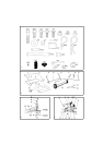
Assembling the hopper bag
Figures and letters in brackets refer to the figures.
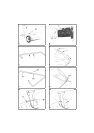
1. See fig. 6, 7. Insert the left-hand, upper hopper
bag tube (1) in the hopper bag flap. Start at the
cut-out in the middle of the hopper bag’s upper
section. The holes in fig. 6 must be facing
down.
2. Install the right-hand, upper hopper bag tube (1)
in the same way and press the tubes together.
3. Secure the tubes by pressing in a plastic plug
(R) through the holes.
4. See fig. 7. Locate the holes in the sides of the
two upper hopper bag tubes. These will be used
later.
5. See fig. 9. Assemble the two lower hopper bag
tubes (3, 4).
6. See fig. 9. Secure the tubes by pressing in a
plastic plug (R) through the holes.
7. Position the lower hopper bag tubes inside the
hopper bag.
8. See fig. 10. Assemble the two upper and lower
hopper bag tubes’ ends using the pins (Q) and
the locking pins (M).
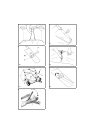
9. See fig. 11. Attach the hopper bag’s front strut
to the lower hopper bag tubes using the pins (O)
and the locking pins (M).
10.See fig. 12. Snap the hopper bag together
around the bag tubes using the snap fasteners.
The hopper bag supports are made of
powerful spring steel. Wear protective
goggles during assembly.
11.See fig. 13. Tension the two sprung struts (11)
in the rear part of the hopper bag.
12.See fig. 14. Locate the holes in the sides of the
hopper bag and make holes with an awl or sim-
ilar.
13.See fig. 15. Install the hopper bag locks (X), the
pins (P) and the locking pins (M) in both sides
of the hopper bag.
NOTE! The hopper bag locks must be able to
move about freely.
14.See fig. 16. Install the line (15).
15.Install the wind protection on the rear upper
section of the hopper bag.
16.See fig. 17, 18. Install the hopper bag on the
brush unit.
USING THE MACHINE
Operating
Be careful when driving on slopes.
The vehicle’s braking characteristics and stability
can be affected by installed accessories or optional
extras. Be particularly careful when driving on
slopes.
Hopper bag height
Set the hopper bag so that its bottom is horizontal
and is 8-10 cm above the ground when driving. See
point 3 under “ASSEMBLY”.
Brush height setting
Set the brushes to the correct height by undoing the
locking wheel and then moving the arm up or
down, see fig. 19. If the arm is moved down, the
brushes are raised. The best results are obtained if
the brushes sweep the top of the grass without
touching the soil below. The brushes must not be
lowered so much that the collector’s wheels slide
or slip.
Speed
• Test which speed produces the best results.
• The speed should be selected so that the grass is
thrown to the rear part of the hopper bag.
• Recommended speed: 4.8 - 6.4 km/h.