


ENGLISH
GB
SAFETY INSTRUCTIONS
1. Never allow anyone to use the collector without
correct instructions.
2. Do not allow children to use the collector.
3. Do not operate the machine too close to naked
flames, as the hopper bag and the brushes are
highly flammable.
4. Do not attempt to remove objects that have be-
come caught up in the brush (e.g. pieces of
string) while the brush is rotating.
5. Move at reduced speed over uneven surfaces
and on slopes to ensure you do not lose control
or the machine does not tip over. Watch out for
holes and other hidden dangers.
6. This collector is not intended to be driven on
public roads. Watch out for traffic when using
the machine close to streets and roads.
7. Ensure that all screws and nuts are tightened so
that the collector is in good condition.
8. Stop and check the collector for damage follow-
ing a collision. Any damage must be repaired
before the collector is used again.
9. Follow all the instructions in this set of instruc-
tions regarding maintenance of the collector.
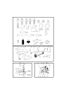
DELIVERY
The delivery comprises a box containing the com-
ponents in fig. 2 as well as a bag. The bag contains
the installation components in fig. 1. The follow-
ing number (x) indicates the quantity of the rele-
vant component.
ASSEMBLY
Tools
The following tools are required for assembly:
• Adjustable wrench
• Box wrenches 3/8 - 7/16 - 1/2 - 9/6
• Screwdriver
• Pliers
•Hammer
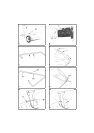
Assembly of brush unit
Figures and letters in brackets refer to the figures.
1. See fig. 3. Undo the existing nuts in the middle
on the front of the brush unit (1). Remove the
flat washers. Position the connecting rod (15)
on the carriage bolts. Install the washers and the
nuts. Do not tighten the nuts yet.
2. See fig. 3. Install the strut (9) on the brush unit
with the aid of two screws (D) with the heads on
the inside of the brush unit. Position two wash-
ers (I) and two locking nuts (G) on the outside.
Do not tighten the nuts yet.
3. See fig. 3. The installation of the angle (14) de-
termines the height of the hopper bag above the
ground (see below).
• The bottom of the hopper bag must be horizon-
tal.
• The distance to the ground must be 8-10 cm
when the height setting arm (7) is in the central
position.
• Never allow the hopper bag to drag on the
ground.
• By installing the angle on the top or bottom of
the connecting rod (15), along with the spacers,
many different heights can be obtained.
• Test which installation best suits the lawnmow-
er in question.
Continue assembly as follows:
Install the angle (14) on the connecting rod with
a screw (B) and a locking nut (F) in the front
hole. Use a longer screw (A), the bracket (V)
and a locking nut (F) in the rear hole. Position
the strut (9) under the bracket (V). Do not tight-
en the nuts yet.
4. Tighten the nuts that were installed under point
3 above. Do not tighten too hard, as this could
deform the tube. Press the connecting rod (15)
down so that the strut (9) comes under the
bracket (V), and press against the screw (A).
Tighten all the screws and nuts that have been
installed.
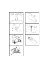
5. See fig. 4. Undo both locking nuts on the height
setting tube (6). Remove the dished washers.
Install the height setting lever (7) on the tube.
Screw in the height setting lever.
6. Press the handle (S) onto the height setting lever
with the finger grip facing forwards.
7. See fig. 4. Install the angle (W) on the connect-
ing rod with a screw (C) and a locking nut (G).