8
ENGLISH
GB
GENERAL
This symbol indicates WARNING. Per-
sonal injury and/or damage to property
may result if the instructions are not
followed carefully.
You must read these instructions for use
and the accompanying pamphlet
“SAFETY INSTRUCTIONS” careful-
ly, before starting up the machine.
SYMBOLS
The following symbols are displayed on the ma-
chine in order to remind you about the safety pre-
cautions and attention necessary when using the
machine.
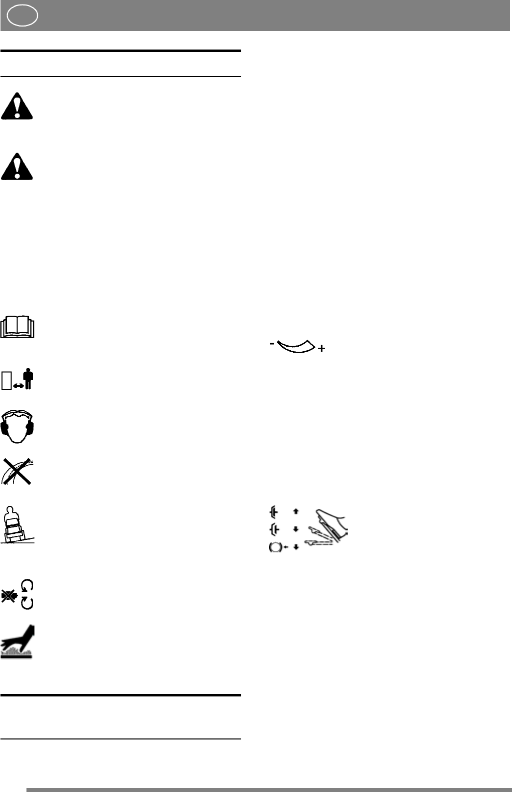
The symbols mean:
Warning!
Read the instruction book and safety man-
ual before using the machine.
Warning!
Beware of objects being flung out. Keep
spectators away.
Warning!
Always use hearing protectors.
Warning!
This machine is not designed to be driven
on public roads.
Warning!
The machine, equipped with original ac-
cessories, must not be driven in any direc-
tion on slopes with a gradient greater than
10º.
Warning!
Clamp risk. Keep hands and feet well
away from the articulated steering joint.
Warning!
Risk for burn injuries. Do not touch the si-
lencer/catalytic converter.
CONTROLS AND
INSTRUMENTS
Items 1 - 20, see figures 1 - 9
1. IMPLEMENT LIFTER
A pedal for raising front-mounted accessories to
the transport position.
To lift up the accessory, press the pedal down asfar
as it will go. Then release the pedal, the implement
lifter is now locked in the lift position.
To lower the accessory, press the pedal down so
that the lock is released. Lower the implement lift-
er to the working position by slowly lifting your
foot from the pedal.
2. LIFT HELP (Pro18 - Pro20)
The implement lifter is complemented with adjust-
able lift help in the form of a gas spring. This facil-
itates lifting heavy accessories.
Under the engine casing, on the top of the rear
bumper, there is a setting crank.
Use this to increase/decrease the lift help.
Screw anti-clockwise to increase the
lift help if heavy accessories are be-
ing used.
Screw clockwise to decrease the lift
help if lighter accessories are being
used.
3A. SERVICE BRAKE/CLUTCH
(Senator)
A pedal that combines both service brake and
clutch. Three positions:
1. Pedal released – forward drive
engaged. The machine will
move if a gear is engaged. Serv-
ice brake not activated.
2. Pedal depressed halfway –
forward drive disengaged, gear
shifting can be performed. Serv-
ice brake not activated.
3. Pedal fully depressed – for-
ward drive disengaged. Service
brake fully activated.
NOTE! You must never regulate the operating
speed by slipping the clutch. Use a suitable gear in-
stead, so that the right speed is obtained.
3B. SERVICE BRAKE (President -
Royal - Pro16 - Pro18 - Pro20)
A pedal that acts upon the machine’s braking sys-


