


25
ENGLISH
EN
10.2Engine casing (2:U)
In order to access the fuel cock, battery
and engine, the machine has an engine
casing that can be opened. The engine cas-
ing is locked with a rubber strap.
The engine casing is opened as follows:
1. Undo the rubber strap (2:V) at the front edge of
the casing.
2. Carefully lift the engine casing back.
Close in the reverse order.
The machine may not be operated un-
less the engine casing is closed and
locked. Risk of burns and crushing in-
juries.
10.3Battery
See “14.8 Battery”.
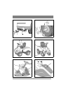
10.4Seat (fig. 4)
1. Remove the following components from the
seat bracket:
• 4 Nuts (for transport locking, not used).
•4 Screws.
• 4 Shoulder washers.
2. Position the seat over the mounting in the seat
bracket.
3. Install the shoulder washers on the screws.
4. Insert the screws with the attached shoulder
washers through the slots in the seat bracket and
the holes in the seat plate. Screw the seat into
place.
Tightening torque: 9±1.7 Nm.
If the screws are tightened more than
9±1.7 Nm, the seat will be damaged.
5. Check that the seat moves easily in the slots in
the bracket.
The seat can be folded. If the machine is parked
outside when it is raining, fold the seat forward to
protect the seat cushion from getting wet.
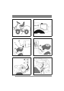
10.5Steering wheel
In order to minimise the axial play in the steering
column, the shim washers (5:B) and/or (5:C) must
be installed on the steering column between the
steering column jacket and the bracket as follows.
1. Install the steering column jacket on the steer-
ing column and secure by knocking in the ten-
sion pin (5:A) approximately 1/3 of its length.
2. Pull the steering column jacket and the steering
column up.
3. From the outside, check whether no washers,
the 0.5 mm washer, the 1.0 mm washer or both
washers can be inserted into the gap. The wash-
er/washers must not be forced in, as there must
be a little axial play.
4. Pull out the cotter pin and dismantle the steering
wheel jacket.
5. Install the washer/washers in accordance with
point 3 above.
6. Install the steering column jacket on the steer-
ing column and secure by knocking in the ten-
sion pin fully. Use a counterhold.
10.6Towing plate
Install the towing plate (6:I) at the rear of the ma-
chine. Use the screws and the nuts (6:J, H).
Tightening torque: 22 Nm.
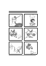
10.7Deck mounts
This only describes installation on the right-hand
axle. Same procedure must be carried out on the
left-hand axle.
1. Lubricate the axle ends and the deck mount’s
bearing surface with oil before installation.
2. Install the deck mounts to the machine accord-
ing to fig. 7.
3. Install the locking pin (7:K) in the hole in the
axle.
10.8Tyre pressure
Check the air pressure in the tyres. Correct air
pressure:
Front: 0.6 bar (9 psi)
Rear: 0.4 bar (6 psi)
10.9Accessories
For the installation of accessories, see separate in-
stallation guide supplied with each accessory.
Note: The cutting deck is regarded as an accessory
here.
11 DESCRIPTION
11.1 Drive
The machine is rear wheel drive.
The rear axle is equipped with a hydrostatic trans-
mission with infinitely variable forward and re-
verse gear ratios.
The rear axle is also equipped with a differential to
facilitate turning.
Front mounted tools are driven by drive belts.
11.2 Steering
The machine is articulated. This means that the
chassis is divided into a front and a rear section,
which can be turned in relation to each other.
The articulated steering means that the machine
can turn around trees and other obstacles with an
extremely small turning radius.