


42
ENGLISH
GB
3.4 Throttle control
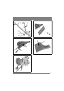
Install the throttle on the left handle according to
fig. 6.
3.5 Throttle cable
1. Install the throttle cable on the engine if not al-
ready installed. See the engine supplier’s man-
ual.
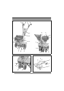
2. Pull up the cable under the support’s (4:U) up-
per section over the screw (5:C).
3. Install the cable in the throttle. See fig. 7.
4. Install the electric cable to the stop control
which is located on top of the throttle.
3.6 Cable for reverse control
Only applies to 40R-G and 50R-B.
The cable is marked R.
1. Pull up the cable under the support’s (4:U) up-
per section over the screw (5:C).
2. Hook the cable in the reverse control (1:A) and
insert the cable in the gap in the cable housing’s
mounting on the left handle.
3. Adjust the cable sleeve if necessary.
3.7 Drive cable
1. Pull up the cable under the support’s (4:U) up-
per section over the screw (5:C).
2. Hook the cable in the drive control (1:B) and in-
sert the cable in the gap in the cable housing’s
mounting on the left handle.
3. Adjust the cable sleeve if necessary.
4 DESCRIPTION
The rotary cultivator is driven by a four-stroke en-
gine and is intended for soil cultivation in private
gardens. The most important parts and controls of
the rotary cultivator are described below.
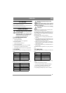
4.1 Reverse control (1:A)
Only applies to 40R-G and 50R-B.
The control is used to start the rotor for reverse
when the engine is running.
The reverse control and drive control (1:B) must
never be activated at the same time.
Control in idle mode (forward) – No drive.
Control moved backwards – The machine
reverses.
4.2 Drive control (1:B)
The control is used to start the rotor for forward
motion when the engine is running.
The reverse control (1:A) and drive control must
never be activated at the same time.
Control in idle mode (down) – No drive.
Control pulled in – Forward operation.
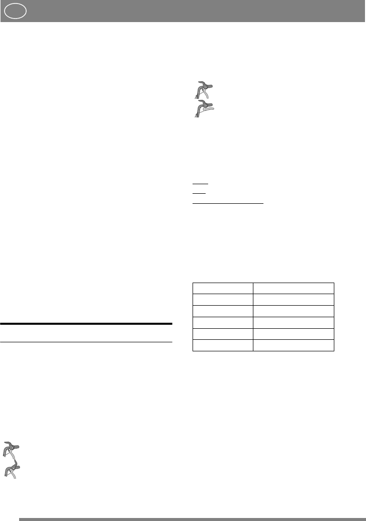
4.3 Throttle and stop (1:C)
The control determines the engine’s rpm and has
start and stop positions.
The throttle control determines the speed and is
used to stop the engine.
Stop
: Control in the rear position.
Idle
: Control 1 cm in front of rear position.
Full throttle and start
: Control in the front position.
4.4 Handle (1:D)
The handle has two handgrips that are used to op-
erate the machine over the area to be cultivated.
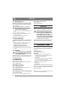
4.5 Fuel cap
Unscrew the fuel cap to fill with petrol. The fuel
cap must always be closed during operation.
The fuel cap is shown according to the table below:
4.6 Protective grille (1:H)
The protective grille must always be installed dur-
ing operation. There are surfaces that become ex-
tremely hot under the protective grille that risk
causing personal injury if touched.
4.7 Cover (1:F)
The cover protects cables and the handle adjust-
ment.
4.8 Handle side adjustment (1:P)
Only applies to 50-G, 50-H and 50R-B.
Release the lever and set the handle to a comfort-
able angle.
Then relock using the lever.
Machine Figure:Position
40-G The engine manual
40R-G The engine manual
50-G The engine manual
50-H The engine manual
50R-B 1:O