


67
ENGLISH
EN
7.7 ADJUSTING THE CONTROL WIRES
When the belts are adjusted or replaced, the control wires
must also be checked/adjusted (see below).
7.7.1 Adjusting auger wire
1. Remove the ignition key.
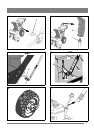
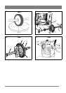
2. Dismantle the belt cover (1) by loosing the screw (2). See
fig. 16.
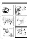
3. Actuate the auger drive lever and observe the tension
pulley. When the auger lever is in its half way of
movement against the handle, the pulley movement shall
stop against the belt (the pulley is allowed to move a few
mm during the last half of movement of the lever). See
fig. 24.
4. If necessary, unhook the spring and adjust the wire at the
screw, connected to the spring. See fig. 25.
5. Reassamble all parts in the reverse order.
7.7.2 Adjusting drive wire, Man
1. Remove the ignition key.
2. Lift the snow thrower forward and rest in on the auger
housing.
3. Loosen the screws (3) and dismantle the bottom plate (2).
See fig. 15.
4. Actuate the auger drive lever and observe the friction
disc. When the auger lever is in its half way of movement
against the handle, the friction disc shall touch the
friction wheel. See fig. 28.
5. If necessary, unhook the wire at the adjusting plate and
replace the wire in a suitable hole. See fig. 26.
6. Reassamble all parts in the reverse order.
7.7.3 Adjusting drive wire, HST
The drive wire, HST has no adjustment. The clutch is
adjusted with the belt tensioning pulley. See “7.6.2”.
7.8 FRICTION WHEEL, MAN
If the snow thrower does not move forward/backward the
problem could be the driving belt, driving control wire or
friction wheel. Check the friction wheel as follows.
7.8.1 Checking the friction wheel
1. Remove the ignition key.
2. Lift the snow thrower forward and rest in on the auger
housing.
3. Loosen the screws (3) and dismantle the bottom plate (2).
See fig. 15.
3. Put the gear stick in neuitral position.
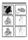
4. With the gear stick in the neutral position, the centre of
friction wheel shall correspond with the centre of the
friction disc. See fig. 28.
5. Adjustments are carried out as described below.
6. Reassemble in the reverse order.
7.8.2 Adjusting the friction wheel
1. Loosen the friction wheel linkage and set the friction
wheel until the measurement in position 4 above is
obtained.
2. If the friction wheel is heavy worn and adjustments
cannot be carried out satisfactorily, replace in accordance
with the following instructions.
3. Otherwise reassemble in the reverse order after adjusting.
7.8.3 Replacing the friction wheel
1. Disassemble the differential according to 7.9.
2. Disassemble the two bearing attachments (M in fig. 23).
3. Disassemble the shaft and bearing attachments. Note the
location of the two washers (17 in fig. 29).
4. Replace the friction wheel on its hub (fig. 30).
5. Reassemble all the parts in the reverse order. Note the
following when reassembling:
- Check that the washers (17 in fig. 29) are correctly
placed.
- Check that the washers (13 in fig. 29) are correctly
placed.
- Check that the shaft (8 in fig. 30) rotates freely.
- Check that the friction wheel and disc drive plate are
totally free from oil and grease.
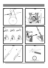
7.9 REPLACING THE DIFFERENTIAL
See fig. 31.
The differential (A) is replaced according to the following
instructions:
1. Remove the ignition key.
2. Lift the snow thrower forward and rest in on the auger
housing.
3. Disassemble the wheels.
4. Loosen the screws (3) and dismantle the bottom plate (2).
See fig. 15.
5. Disassemble the bearing housings (B) with bearings at
both sides.
6. Loosen the intermediate shaft (C) by disassembling the
bearing screws (D) at both sides.
7. Slacken the chain tension by loosening the support
bearing attachment (E). The support bearing attachment
is loosened by disassembling the two screws at the top.
8. Remove the chain from the differential.
9. Pull out the shafts from the differential and remove the
differential.
10. Check the chains. Replace if required. The chains shall
not be lubricated. They are factory lubricated. Excessive
grease can spoil the friction if it reach the friction wheel
or the friction disc.
11. Check the bearings for dissonance and uneven friction at
rotation. Replace if required.
12. Reassemble all parts in the reverse order.
7.10 REPLACING THE SHEAR BOLTS
The auger is fastened to the shaft by special bolts that are
designed to break if something gets stuck in the auger
housing.
Always use genuine spare parts. Other types of
bolts could cause serious damage to the machine.
1. Stop the engine.
2. Disconnect the ignition cable from the spark plug.
3. Ensure all the rotating parts have stopped.
4. Remove the object that has fastened in the auger.
5. Lubricate the auger shaft (see above).
6. Aligne the holes in the shaft and auger.
7. Remove the broken bolt parts.
8. Assemble a new original shear bolt.