


66
ENGLISH
EN
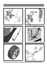
7.4 THE AUGER BELT
7.4.1 Replacing the auger belt
Man, see fig. 18, 19.
HST, see fig. 20, 21.
1. Remove the ignition key.
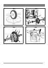
2. Loosen the screws (3) and dismantle the bottom plate (2).
See fig. 16.
3. Remove the belt protective cover (1) by loosening the
screws (2). See fig. 16.
4. Loosen the belt guide (E) at the engine belt disc.
5. Remove the tension pulley (B) from the belt.
6. Replace the belt (G). NOTE! Only genuine STIGA belts
are to be used.
7. Adjust the belt tension according to the instructions
below.
8. Assemble the belt guide (E).
9. Reassemble the belt protection. See fig. 16.
10. Adjust the control wire according to the instructions
“7.7”.
7.4.2 Check and adjustment of the auger belt
Man, see fig. 18, 19.
HST, see fig. 20, 21.
1. Remove the ignition key.
2. Remove the belt protective cover (1) by loosening the
screws (2). See fig. 16.
3. Loosen the tension-pulley (B) and move it about 3 mm
towards the belt.
4. Tighten the tension pulley nut.
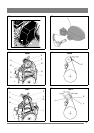
5. Check the belt tension by pressing down the auger clutch
lever. With a finger, you should be able to push the belt
about 12 - 13 mm without any great power (fig. 22).
6. Repeat the above procedure if further adjustment is
required.
7. Reassemble the belt protection. See fig. 16.
7.4.3 Adjustment of auger belt guide
Man, see fig. 18, 19.
HST, see fig. 20, 21.
1. Remove the ignition key.
2. Remove the belt protective cover (1) by loosening the
screws (2). See fig. 16.
3. Activate the auger clutch lever (20) in fig. 1.
4. Check the distance between the belt guide and the belt.
See fig. 19/21 according the distance.
5. If adjustment is required, loosen the screw to the belt
guide and set the correct distance.
6. Tighten the screw properly.
7. Reassemble the belt protection.
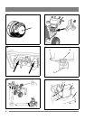
7.5 DRIVE BELT, MAN
7.5.1 Replacing the drive belt, Man
See fig. 18, 19.
1. Dismantle the auger belt as described above.
2. Remove the left wheel.
3. Remove the locking ring (C) from the swing plate shaft
(D). Pull out the shaft.
4. Remove the spring (H).
5. Replace the belt (I). NOTE! Only genuine STIGA belts
are to be used.
6. Check that the tension pulley (A) is in line with the belt
(I).
7. Reassemble the spring (H), shaft (D) and locking ring
(C).
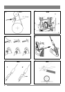
8. Check that the underside of the disc drive plate (Q) is
situated between the marks (N). See fig. 23.
NOTE! If the machine still does not drive properly,
recheck the location of the disc drive plate (Q).
9. Reassemble all parts in the reverse order.
7.5.2 Adjustment of drive belt, Man
The belt has a spring-loaded tension pulley. Adjustment is
not required. If the belt slips, change it.
7.6 DRIVE BELT, HST
7.6.1 Replacing the drive belt, HST
See fig. 20, 21.
1. Dismantle the auger belt as described above.
2. Loosen the beltguides (J, L) at the motor pulley.
3. Work off the used belt and fit the new. NOTE! Only
genuine STIGA belts are to be used.
4. Assemble the belt guides (J, L) at the motor pulley.
Adjust the belt guide according to the instructions below.
5. Reassemble all parts in the reverse order.
6. Adjust the control wire as described further “7.7”.
7.6.2 Adjusting the drive belt, HST
1. Dismantle the belt cover (1) by loosing the screw (2). See
fig. 16.
2. Adjust the tension pulley (A in fig. 20) until a belt play of
about 45 mm. See fig. 32.
Do not overtighten the belt. This will damage the
belt and the bearings. Always check the belt
tension according to the instructions below before
using the machine.
3. Check the adjustment according to the instructions
below.
4. Reassemble the belt cover. See fig. 16.
7.6.3 Check the drive belt, HST
1. Disconnect the wheel locks.
2. Set the speed lever in the neutral position. Do not activate
the clutch lever.
3. Start the engine and move the speed lever slow forwards.
If the drive shafts rotate, the belt is too tight, and the
tension pulley (A in fig. 20) shall be loosened and moved
from the belt.
4. If the tension pulley was moved redo the adjustment and
the check as described above.