5
ENGLISH
GB
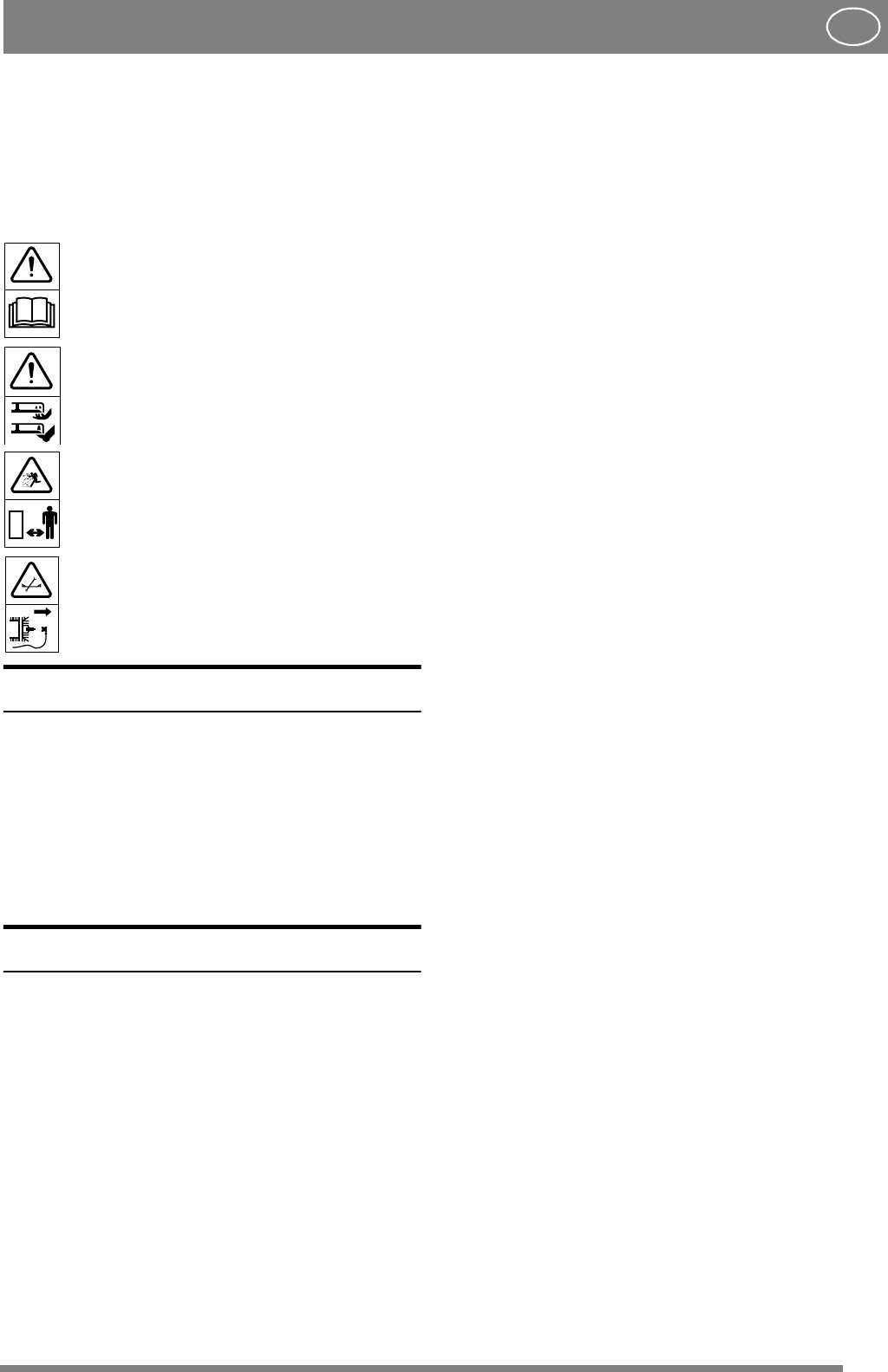
SYMBOLS
The following symbols can be found on the
machine to remind you of the care and attention
that are required during use.
The symbols mean:
Warning!
Read the instruction manual and the safety
manual before using the machine.
Warning!
Do not insert your hands or feet under the
cover when the machine is in operation.
Warning!
Watch out for discarded objects. Keep
onlookers away.
Warning!
Before starting repair work, remove the
spark plug cable from the spark plug.
INTRODUCTION
107 M
This cutting deck is available as standard in two
versions:
- with mechanical setting of the cutting height
(item no. 13-2930).
- with factory-fitted, electrical setting
of the cutting height (item no. 13-2934).
INSTALLATION
DECK ARMS
1. Install the left and right deck arms in the cutting
deck’s front two corners. Use the existing screw
and flat washer (fig. 1). Tighten the screw. After
tightening, it should be possible to move the deck
arms up and down.
2. Do not hook the rear part of the deck arms onto
the deck yet (See “Cutting deck” point 7 below).
CUTTING DECK
1. Place the cutting deck in front of the machine.
Set the maximum cutting height.
2. Remove the locking pin and the outermost flat
washer from the machine’s steering knuckle.
3. Thread one deck arm onto the steering knuckle.
Place the flat washer on the steering knuckle and
secure with the locking pin. Repeat on the other
side (fig. 2).
4. Force the V-belt onto the machine’s pulley A
(fig. 3).
5. Lift up the deck’s rear part past the catch until it
drops down. When the weight of the deck is resting
on the upper side of the catch, the installation is
correct (fig. 4).
6. Tension the belt with belt idler B. The belt idler
should be on the inside of the belt and pull out to
the left (viewed from the driver’s position).
7. Screw the lift spring into the machine’s lifting
arm.
(fig. 5).
8. Connect the electrical contact to the socket on
the side of the machine (only applies to item no.
13-2934), (fig. 6).
SETTING
In order for the deck to cut evenly and attractively,
it has to be correctly adjusted:
1. Make sure the air pressure in the tyres is correct:
Front: 0.4 bar (6 psi).
Rear: 1.2 bar (17 psi).
2. Place the machine on a level floor. Undo the
screws on either side of the deck (fig. 6).
3. On the side of the deck arm are four short and
two long lines. The upper long line (A) is the basic
setting for a machine with 16” tyres. The lower (B)
for a machine with 17” tyres (fig. 7).
Note: Villa has 16” wheels.
Depending on the length of the grass, the deck can
be adjusted in various ways:
4a. Cutting normal length grass:
Adjustthedecksothatthefrontandrearedgeof
the cover are the same height above the floor. This
position gives the best ‘Multiclip effect’, i.e. the
grass is cut up best.
4b. Cutting long grass:
Adjust the deck so that the cover’s rear edge is
higher than the front edge. This position means
that the deck can release the grass more easily at
the rear edge.


