


8
9
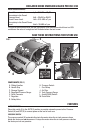
SAFETY VALVE
If the Pressure Switch (H) does not shut off the air compressor at its cut-out pressure setting,
the safety valve (G) will protect against high pressure by popping out at its factory set pressure
(slightly higher than the Pressure Switch (H) cut-out setting).
CHECK VALVE
When the air compressor is operating, the check valve is open, allowing compressed air to
enter the air tank. When the air compressor reaches cut-out pressure, the check valve closes,
allowing air pressure to remain inside the air tank.
TANK PRESSURE GAUGE
Thetankpressuregauge(K)indicatesthereserveairpressureinthetank.
REGULATED PRESSURE GAUGE
The regulated pressure gauge (D) indicates the air pressure available at the outlet side of the
Regulator (F). This pressure is controlled by the Regulator (F).
REGULATOR
The regulator (F) controls the air pressure shown on the Regulated Pressure Gauge (D).
Pull the knob out and turn clockwise to increase pressure and counterclockwise to decrease
pressure. When the desired pressure is reached push knob in to lock in place. The regulated
pressure range is 7–150 psi.
Risk of Bursting. Too much air pressure causes a hazardous risk of bursting.
Check the manufacturer’s maximum pressure rating for air tools and accessories. The Regulator
(F) outlet pressure setting must never exceed the maximum pressure rating of the tool or
accessory.
UNIVERSAL QUICK CONNECT BODY
The universal quick connect body (E) accepts the three most popular styles of quick connect
plugs: Industrial, automotive, and ARO. One hand push-to-connect operation makes connec-
tions simple and easy. The two quick connect bodies allow the use of two tools at the same time.
DRAIN VALVE
Thedrainvalve(M)islocatedatthebaseoftheairtankandisusedtodraincondensationatthe
end of each use. See Draining Air Tank under Maintenance.
COOLING SYSTEM
This compressor contains an advanced design cooling system. It is normal for this fan to blow
air through the vent holes in large amounts. The cooling system is working when air is expelled.
AIR COMPRESSOR PUMP
The pump compresses air into the air tank. Working air is not available until the compressor has
raised the air tank pressure above that required at the air outlet.
AIR INTAKE FILTER
The filter (J) is designed to clean air entering the pump. To ensure the pump continually receives
a clean, cool, and dry air supply the filter must always be clean and the filter intake must be free
from obstructions.
MOTOR OVERLOAD PROTECTOR
The motor has a thermal overload protector. If the motor overheats for any reason, the overload
protector will shut off the motor. The motor must be allowed to cool down before restarting. To
restart:
1. SettheAuto/OfflevertoOffandunplugunit.
2. Allow the motor to cool.
3. Plug the power cord into the correct branch circuit receptacle.
4. SettheAuto/OfflevertoAUTOposition.