


5
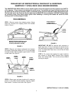
STEP 6: Make sure all nuts and bolts are tight. Set-up
is now complete for self-propelled models without
electric start capability. Proceed to checklist found on
last page of this instruction to prepare mower for use.
For electric start models, continue to the “Electric Start
Models” Section.
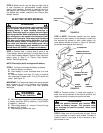
ELECTRIC START MODELS
WARNING
The electrolyte (acid) produces a highly explosive gas.
Keep all sparks, flame and fire away from area when
charging battery or when handling electrolyte or
battery. Electrolyte (acid) is a highly corrosive liquid.
Wear eye protection. Wash affected areas immediately
after having eye or skin contact with electrolyte (acid).
Battery acid is corrosive. Rinse empty acid containers
with water and mutilate before discarding. If acid is
spilled on battery, bench, or clothing, etc. Flush with
clear water and neutralize with baking soda. Never
attempt to charge battery while installed on the walk
behind. Never use “BOOST” chargers on the battery.
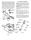
STEP 1: Perform Step 1 through Step 6 found in the
“Push Models” Section and Step 1 through Step 6 found
in the “Self-Propelled Models” Section of this instruction
before going to Step 2 of “Electric Start Models”
Section. Remove grass bag.
NOTE: Electrolyte (Acid) is shipped with battery.
STEP 2: Activate and charge the battery as follows:
A. Remove battery from carton.
B. Place battery in a well ventilated area on a level
surface.
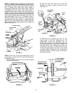
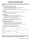
C. Remove battery cell caps. Fill cells as required
with electrolyte to proper level. Fill to 3/16” above cell
plates. See Figure 15.
IMPORTANT: 3/16” above cell plates is the recommended
level. However do not try to measure this dimension.
Never place anything in battery other than specified
electrolyte.
WARNING
DO NOT OVERFILL!
D. With cell caps removed, connect battery charger
to battery terminals; RED to positive (+) and BLACK
to negative (-) terminal.
E. Slow charge battery at 1 amp for 2 hours to bring
the battery to full charge.
F. After charging, reinstall cell caps.
FIGURE 15
STEP 3: NOTE: Disconnect transfer rod from speed
control rod to gain access to top bracket. Loosen bolt
that secures top bracket to deck. Install battery into
lower battery bracket as shown in Figure 16. Reinstall
top bracket and retighten bolt securely.
FIGURE 16
STEP 4: Connect positive (+) cable and negative (-)
cable from wiring harness to the positive terminal and
negative terminal on battery using nuts and bolts.
WARNING
Shield the positive terminal with terminal cover
located on battery harness. This prevents metal
from touching the positive terminal, which could
cause sparks.
STEP 5: Make sure all nuts and bolts are tight. Set-up
is now complete for electric start models. Proceed to
checklist found on last page of this instruction to pre-
pare mower for use.
CELL
BATTERY
PLATES
ELECTROLYTE
LEVEL
TOP OF
PLATES
TOP BRACKET
CONNECT BATTERY
HARNESS TO BATTERY
BATTERY
CONNECT BATTERY
HARNESS TO MAIN
HARNESS
MAIN
HARNESS
LOWER
BRACKET