


21
Section 4 - ADJUSTMENTS & REPAIR
WARNING
DO NOT attempt any adjustments, maintenance,
service or repairs with the engine running. STOP
engine. STOP blade. Engage parking brake. Remove
key. Remove spark plug wire from spark plug and
secure away from plug. Engine and components are
HOT. Avoid serious burns, allow all parts to cool
before working on machine. Fuel Filler Cap and vent
must be closed securely to prevent fuel spillage.
4.2 MOWER DECK & COMPONENT ADJUSTMENTS
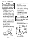
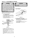
4.2.2. BLADE BRAKE ADJUSTMENT
2. Remove Belt Cover. Refer to Section “BLADE
BELT COVER REMOVAL”.
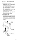
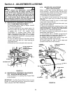
3. Remove retaining pin from eyebolt swivel. Lift
swivel out of deck rail. See Figure 4.3. If dimension
is greater than 3-1/4”, turn eyebolt swivel
CLOCKWISE to increase brake tension and
reduce clearance between Blade Lever and Latch
Plate. If dimension is less than 3”, turn eyebolt
swivel COUNTERCLOCKWISE to decrease brake
tension. See Figure 4.3.
4. Once the desired clearance has been attained,
reinstall swivel onto deck rail. Insert retaining pin
into eyebolt swivel.
5. Reinstall belt cover and tighten bolts securely.
FIGURE 4.3
4.2 MOWER DECK & COMPONENT ADJUSTMENTS
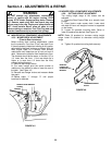
4.2.3. ADJUSTING MOWER BLADE
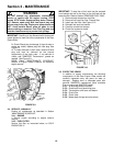
Follow procedures for standing Rear Engine Rider
on rear bumper.
IMPORTANT: If the Rear Engine Rider will be on its rear
bumper for longer than two hours, remove the battery.
Refer to Section “BATTERY REMOVAL”.
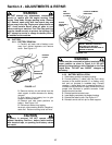
4.2.4. MOWER DECK ADJUSTMENT
(Side To Side Levelness)
Before making deck leveling adjustments, check
the tire pressure. Front tires 12 psi, rear tires 12 psi.
If tires are properly inflated and mowing is still uneven,
adjust side-to-side deck levelness as follows:
1. Place Rider on a smooth level surface.
2. Turn engine off and remove key, remove spark
plug wire from spark plug and secure wire away
from plug.
3. Place a piece of angle iron, pipe, or similar object
under center of deck at the rear.
4. Remove rear hanger chains and allow center, rear
of deck to rest on angle iron.
5. Measure the distance from blade tips to floor. If the
measurement is within 1/8” from side-to-side, the deck
attitude is satisfactory. If difference from side-to-side is
greater than 1/8”, continue with adjustment.
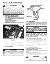
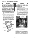
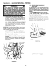
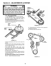
6. Loosen the shoulder bolt retaining the left side of
blade pedals. See Figure 4.4.
7. Turn eccentric “UP” or “DOWN” as required until
blade tips are within 1/8” of each other. See Figure 4.4.
8. Tighten shoulder bolt loosened in step “6”.
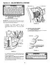
9. Readjust rear hanger chain pivots to align with
holes in support brackets. See Figure 4.5.
10. Remove angle iron, pipe, or similar object and
proceed to check front to rear levelness.
FIGURE 4.4
ROTATE SWIVEL ON
EYE BOLT TO
ACHIEVE CORRECT
CLEARANCE
EYEBOLT
EYE BOLT
SWIVEL
RETAINING PIN
LOOSEN
SHOULDER
BOLT
TURN ECCENTRIC AS
REQUIRED
BLADE
PEDAL
BLADE PEDAL
ECCENTRIC
LIFT
ARM
SHOULDER
BOLT