


15
Section 3 – MAINTENANCE
3.2 SERVICE - AFTER FIRST 5 HOURS
3.2.8. REVERSE LOCKOUT MECHANISM
Check function of Reverse Lockout Mechanism
with engine off.
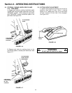
1. Depress and hold blade pedals.
2. Depress and hold clutch/brake pedal.
3. Shift lever must not go into reverse.
WARNING
DO NOT operate machine if Reverse Lockout
Mechanism is not functioning properly. Contact
your SNAPPER dealer immediately for assistance.
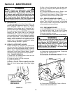
3.2.9. LUBRICATION – GREASE FITTINGS
The following components on the Rear Engine
Rider are equipped with grease fittings and require
periodic lubrication. Apply General Purpose grease
(NLGI No.2) with a grease gun.
1. Front Wheel Bearings. Refer to Section
“FRONT WHEEL BEARINGS – LUBRICATION”.
2. Rear Axle Bearing. Refer to Section “REAR
AXLE BEARING – LUBRICATION”.
3. Mower Blade Spindle. Refer to Section
“MOWER BLADE SPINDLE – LUBRICATION”.
3.3 SERVICE - EVERY 25 OPERATING HOURS
3.3.1. Perform all service required after the first 5
hours of operation. Refer to Section “SERVICE –
AFTER 5 HOURS”.
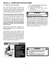
WARNING
DO NOT attempt any adjustments, maintenance,
service or repairs with the engine running. Stop
engine. Stop blade. Engage parking brake. Remove
key. Remove spark plug wire from spark plug and
secure away from plug. Engine and components are
HOT. Avoid serious burns, allow all parts to cool
before working on machine. Fuel Filler Cap and
Vent must be closed securely to prevent fuel
spillage.
3.3.1. CHECK ENGINE
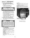
1. Engine Cooling System
The engine cooling system consists of an engine
shroud and engine fins. These should be kept
clean and free of debris as needed or cleaned.
2. Engine Oil
Change engine oil. See Section on CHANGE
ENGINE OIL. Refer to engine owner’s manual for oil
specifications.
3. Oil Filter
Change engine oil filter. Refer to engine owner’s
manual for filter specifications.
4. Fuel Filter
Refer to engine owner’s manual for service
instructions.
5. Air Filter
Refer to engine owner’s manual for service
instructions.
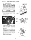
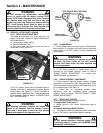
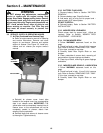
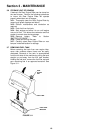
a. Change air filter. Remove bolts that secure air
cleaner cover. See Figure 3.4.
IMPORTANT: When cover is removed, you are
viewing the carburetor side of the air filter, which will
appear clean. Remove filter and pre-cleaner for
inspection.
FIGURE 3.4
(Continued On Next Page)
AIR CLEANER
COVER
AIR CLEANER
RETAINING BOLTS
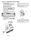
NOTE: YELLOW TABS MUST BE
COMPLETELY INSERTED INTO SLOTS