


15
Section 4 - REPAIR & ADJUSTMENTS
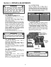
WARNING
DO NOT attempt any maintenance, adjustments or
service with engine and blade running. STOP engine
and blade. Disconnect spark plug wire and secure
away from spark plug. Engine and components are
HOT. Avoid serious burns, allow sufficient time for
all components to cool.
4.3 GROUND SPEED CONTROL ADJUSTMENT
4.3.1. IDLER SPRING TENSION ADJUSTMENT
Correct idler spring tension assures that mower will
achieve fastest attainable speed when ground
speed control lover is placed in ‘FAST’ position.
1. Remove rear cover from mower. Refer to
Section “Rear Cover Removal & Installation”.
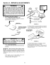
2. Idler spring tension is adjusted properly when:
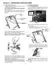
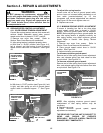
a. With lever in ‘SLOW’ position (see Figure 4.4),
belt is relaxed, and idler spring on end of ground
speed control cable has no extension. See Figure
4.6.
FIGURE 4.6
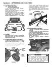
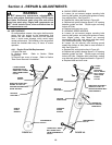
b. With lever in ‘FAST’ position (see Figure 4.4), belt
is tight, and idler spring on end of ground speed
control cable is extended approx. 1”. See Figure
4.7.
FIGURE 4.7
To adjust idler spring tension:
Loosen outer nut on end of ground speed cable,
and run inner nut in toward cable (clockwise) or out
from cable (counterclockwise) by 1/2 turn
increments until correct adjustments are attained.
See Figure 4.6. Be sure to tighten outer nut.
3. Replace rear cover.
4.3.2. MINIMUM GROUND SPEED ADJUSTMENT
If mower is traveling too fast or too slow when
ground speed control lever is placed in ‘SLOW’
position, minimum ground speed can be adjusted.
NOTE: Before adjusting minimum ground speed, be
sure idler spring tension is adjusted correctly, as
idler spring tension may affect minimum ground
speed. Refer to Section “Idler Spring Tension
Adjustment”.
1. Remove rear cover from mower. Refer to
Section “Rear Cover Removal & Installation”.
2. Place ground speed control lever in ‘SLOW’
position. See Figure 4.4.
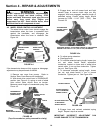
3. Adjust minimum ground speed:
To decrease minimum ground speed:
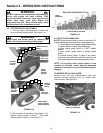
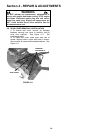
Remove end of idler spring from current adjustment
hole, and relocate spring one hole closer to idler
arm pivot bolt. See Figure 4.7a.
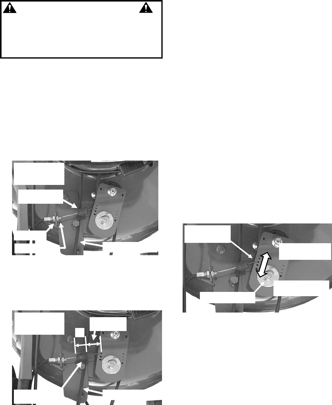
To increase minimum ground speed:
Remove end of idler spring from current adjustment
hole, and relocate spring one hole farther from idler
arm pivot bolt. See Figure 4.7a.
FIGURE 4.7a
NOTE: After adjusting minimum ground speed,
readjustment of idler spring tension may be
necessary.
4. Replace rear cover.
5. Check minimum ground speed; repeat
adjustment as necessary.
THE DRIVE BELT ON THIS UNIT IS SUBJECT TO
WEAR, AND SHOULD BE CHECKED
REGULARLY. REPLACE A WORN, FRAYED OR
DAMAGED BELT IMMEDIATELY.
GROUND SPEED
LEVER IN ‘SLOW’
POSITION
SPRING HAS NO
TENSION
GROUND SPEED
LEVER IN ‘FAST’
POSITION
BELT IS RELAXED
SPRING LENGTH
EXTENDED 1”
BELT IS TIGHT
1”
INNER NUT
OUTER NUT
UNEXTENDED
LENGTH
ADJUSTMENT
HOLES
DECREASE MINIMUM
GROUND SPEED
INCREASE MINIMUM
GROUND SPEED
IDLER PIVOT BOLT