


18
SECTION 4 - SERVICE
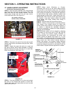
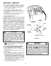
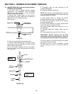
4.2.3. HYDRAULIC PUMP BELT REMOVAL (Continued)
2. Loosen Nut on Belt Guide at rear of Engine Pulley
and remove Cutter Deck Belt from Engine Pulley.
3. Remove Hydraulic Pump Belt.
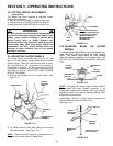
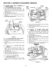
4.2.4. HYDRAULIC PUMP BELT INSTALLATION
1. STOP ENGINE! Place Hydraulic Belt on Engine and
Pump Pulleys.
2. Attach Idler Spring to Bolt and reattach Nut to Bolt.
3. Place Cutter Deck Belt on Engine Pulley.
4.2.5. REPLACEMENT PARTS
To retain the quality of your Machine, use genuine
SNAPPER replacement parts only. Contact your local
SNAPPER Dealer for parts and service and service
assistance. For the correct part or information for your
Machine, always mention Model and Serial Number of
Power Unit and mower Attachment. We recommend
returning your Machine to an authorized SNAPPER
Dealer on a yearly basis for inspection and addition of
any new devices which might upgrade the performance
and SAFETY of your Machine. For the nearest
SNAPPER Dealer, check the yellow pages under the
heading, LAWN MOWERS. For Engine Parts and
Service, look for the Engine Manufacturer’s Dealers
under the heading, ENGINES - GASOLINE.
WARNING
DO NOT attempt any maintenance adjustments or
service with the engine running. Stop engine. Stop
blades. Latch Traction Controls in neutral. Move
Speed Control lever to SLOW. Remove key.
Disconnect spark plug wires from spark plugs and
secure wires away from spark plugs. Engine and
components are HOT. Avoid serious burns by
allowing all parts sufficient time to cool before
working on machine.
NOTE: All Mid-Size Machines should be tilted with
Engine Carburetor side UP.
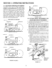
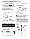
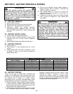
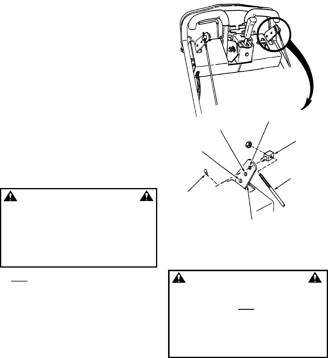
4.3 MACHINE SPEED CONTROL RANGES
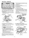
4.3.1. TO CHANGE MACHINE SPEED RANGES
1. Move Traction Control Levers and Neutral Latch
Lever into neutral.
2. Turn Key to STOP position and remove Key from
Ignition Switch.
3. Remove Hairpins from Swivels on Traction Control
Arms on Right and Left Hand side. See Figure 4.5.
4. Push Swivel out from each Traction Control Arm and
insert Swivel into newly selected speed range. (No
adjustment should be necessary to maintain neutral
setting after changing speed range.) If machine does
require adjustment Refer to Section “TRACTION
CONTROL NEUTRAL ADJUSTMENT”.
5. Start the Engine and resume using the Machine at
the newly selected speed range.
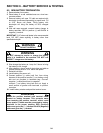
FIGURE 4.5
WARNING
The SNAPPER Pro Hydro Mowers have a Transport
Speed, which allows the machine to travel forward at a
speed of 6 MPH - it is NOT to be used while walking! Use
the Transport Speed ONLY when the machine is
equipped with a Riding Sulky! DO NOT make sharp
turns at high speed! The machine has “zero-turn”
capability; DO NOT use “zero-turn” at high speed.
During initial training time with machine, it is advised
that the Operator(s) practice with the Speed Control
Lever in the slowest travel speed position and Blade
Engagement Switch in the OFF position
MEDIUM SPEED
0 - 4.2 MPH
HIGH SPEED
0 - 6 MPH
SWIVEL
TRACTION
CONTROL
ROD
TRACTION CONTROL ARM
SELF LOCK
COTTER PIN
LOW SPEED
0 - 2.5 MPH