


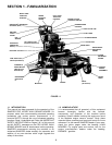
12
SECTION 3 - OPERATING INSTRUCTIONS
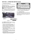
3.8 CUTTING HEIGHT ADJUSTMENT
(Fixed Decks)
The Mower has three methods of adjusting cutting
height listed as follows:
1. Moving position of BLADE on cutter spindle shaft.
2. Moving position of CASTER WHEEL on support.
3. Moving position of MOWER DECK on power unit.
WARNING
DO NOT attempt any maintenance, adjustments or
service with the engine running. Stop engine. Stop
blades. Latch Traction Controls in neutral. Move
Speed Control lever to SLOW. Remove key.
Disconnect spark plug wires from spark plugs and
secure wires away from spark plugs. Engine and
components are HOT. Avoid serious burns by
allowing all parts sufficient time to cool before
working on machine.
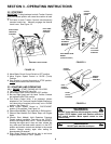
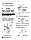
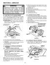
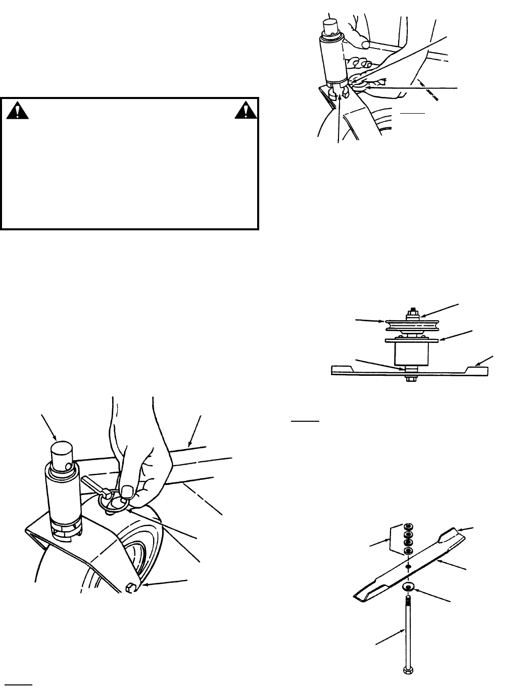
3.9 ADJUSTING CASTER WHEELS
The Caster Wheel Assemblies have four (4) 1/2” and
one (1) 1/4” thick Spacer. When placed above or below
Caster Support Tube, the Operator can raise or lower
the cutting height in 1/2” increments, thus providing a
“Quick-Adjust” method. The deck mounting has to be
changed to correspond with the Caster repositioning as
described in Section “ADJUSTING FIXED MOWER
DECK ATTACHMENT”.
1. Remove the Retainer Pin from Caster Shaft. See
Figure 3.12.
FIGURE 3.12
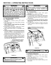
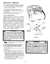
2. Lift Caster Support Tube while adding or removing
the bottom Spacer. See Figure 3.13.
NOTE: Remove (or add) Spacers by rotating slots so
they align with the flat area on Caster Shaft.
FIGURE 3.13
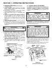
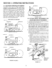
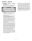
3.10 ADJUSTING BLADE ON CUTTER
SPINDLE
To change cutting height of Blades, move the Spacers from
under the Cutter Housing to above the Cutter Housing
Pulley. Each Spacer moved above the Cutter Housing
Pulley will provide an additional 1/4” of cutting height. DO
NOT PUT ANY SPACERS BELOW BLADE! See Figure
3.14.
FIGURE 3.14
NOTE: Changing the cutting height of Blades DOES
NOT change the Deck ground clearance. If an
undesirable cutting pattern results, then cutting height
adjustment MUST be made by adjusting Mower Deck
height and Caster Wheels.
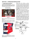
Install Blades (Air-Lift UP) with retaining hardware as
shown below and tighten to 70-80 ft. lbs.
See Figure 3.15.
FIGURE 3.15
CASTER SHAFT
CASTER
SUPPORT
TUBE
RETAINER
PIN
CASTER WHEEL
ASSEMBLY
SLOT
SPACERS
FLAT
AREA
NOTE! THOSE SPACERS
REMOVED FROM BOTTOM
OF CASTER SHOULD BE
REINSTALLED AT TOP
BEFORE INSERTING
RETAINER PIN.
CUTTER
HOUSING
PULLEY
SPACERS ON
BOTTOM
SPACERS ON
TOP
CUTTER
HOUSING
BLADE
HEIGHT
ADJUSTING
SPACERS
MOUNTING
BOLT
AIR LIFT
BLADE
BEVELED
WASHER
TIGHTEN TO 70-80
FOOT POUNDS