


Troubleshooting, Adjustments, & Service
25
NEUTRAL ADJUSTMENTS
If the machine creeps while the motion control levers are
locked into their neutral locked positions, then it may be
necessary to adjust the link rods.
Perform this adjustment on a hard level surface such as
a concrete floor.
IMPORTANT NOTE:This adjustment should be per-
formed with the engine OFF. Perform the adjustment,
then start the engine to check the adjustment. If further
adjustment is required, stop the engine before perform-
ing the adjustment.
1. Determine which wheel is creeping. The left side
transmission and link rod control the left wheel, the
right link rod controls the right wheel.
2. Disengage the PTO, lock the motion control levers
into their neutral locked positions, turn the engine off,
remove the key, and wait for all moving parts to stop.
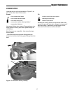
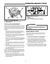
3. Remove the hardware (C, Figure 23) connecting the
rod end (B) to the control bracket weldment (A).
Note: The rod end is located under the fender beside
the operator seat.
4. Loosen the rod end jam nut (B).
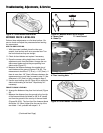
If the transmission is creeping forward, turn the rod
end in (clockwise) one or two turns to shorten the link
rod (E).
If the transmission is creeping in reverse, turn the rod
end out (counterclockwise) one to two turns to length-
en the link rod.
5. Retighten the jam nut, and reconnect the rod end to
the control bracket weldment.
6. Start the unit and check for transmission creep.
Repeat steps 2-5 if necessary.
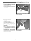
7. Once the correct adjustment is achieved, check
adjustment of the compression spring (F). With the
motion control levers in their neutral locked positions,
the spring should have no compression, and should
have approximately 1/16-1/8” of free play between the
washers at either end. Turn the two adjustment nuts
(G) in or out until the desired adjustment is achieved.
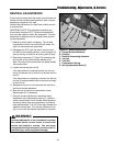
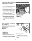
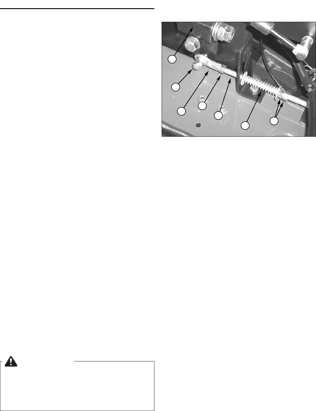
Figure 23. Neutral Adjustment
A. Control Bracket Weldment
B. Rod End
C. Rod End Connecting Hardware
D. Jam Nut
E. Link Rod
F. Compression Spring
G. Spring Adjustment Nuts (2)
B
D
C
E
F
A
G
WARNING
Incorrect adjustment of the compression springs
can cause motion control levers to move from
neutral into forward or reverse. This can cause
unexpected machine movement, and may result in
possible injury and/or equipment damage.