


7
Section 2 - OPERATING INSTRUCTIONS
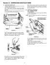
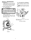
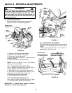
2.2.2. PROPELLING MOWER
(Self Propelled Models Only)
1. Move ground speed control to the desired speed
position. See Figure 2.4.
2. Start engine. Refer to Section “Starting &
Operation”.
3. Move wheel drive control against handle to
engage wheel drive and propel mower forward.
Forward speed can be adjusted while the mower is
moving by changing position of the ground speed
control. See Figure 2.4.
FIGURE 2.4
2.3 STOPPING
Stop engine and blade by releasing the blade
control. Stop forward motion of mower by releasing
the wheel drive control.
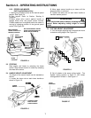
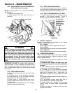
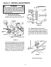
2.4 HANDLE HEIGHT ADJUSTMENT
The height of the mower handle can be adjusted as
follows:
1. Loosen the lower nuts on each lower handle as
shown in Figure 2.5.
FIGURE 2.5
2. Move upper mower handle up or down until the
desired position is achieved.
3. Tighten the lower nuts on each lower handle to
maintain desired position.
WARNING
STOP engine and mower blade by releasing the blade
control before adjusting cutting height or handle
height.
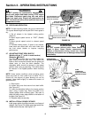
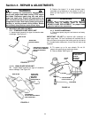
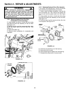
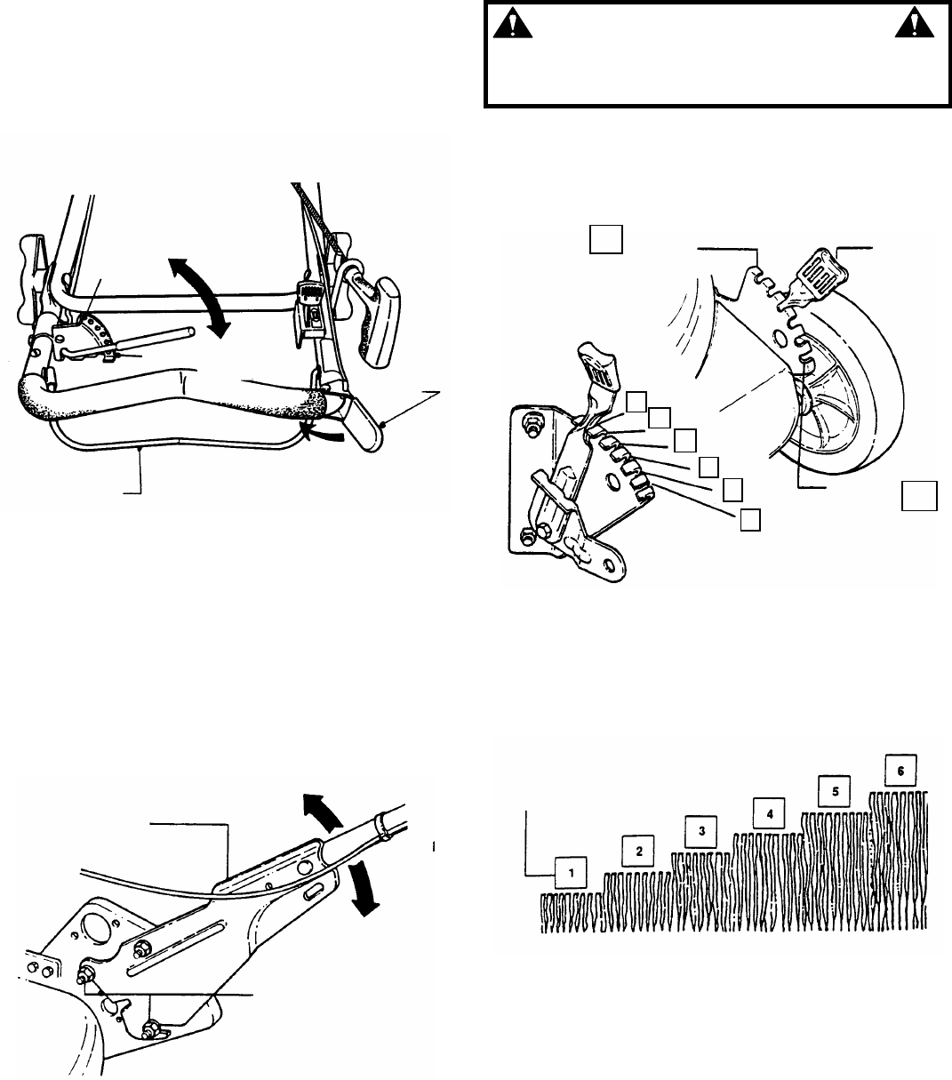
2.5 CUTTING HEIGHT ADJUSTMENT
1. Pull the height adjusting latch outward and move
to desired cutting height. See Figure 2.6.
FIGURE 2.6
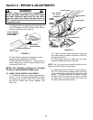
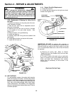
2. Set all wheels at the same cutting height. The
highest cutting position is Notch 6. The lowest
cutting position is Notch 1. See Figure 2.7.
FIGURE 2.7
MOVE GROUND
SPEED CONTROL TO
DESIRED POSITION
RECYCLING MODEL SHOWN
(ROPE START MOUNTED ON
RIGHT SIDE OF HANDLE)
(SLOW)
FIRST SPEED
POSITION
(FAST)
SIXTH SPEED
POSITION
WHEEL DRIVE
CONTROL
FIRST
BLADE
CONTROL
SIXTH
HIGHER
LOWER
LOOSEN LOWER
NUTS ON EACH
LOWER HANDLE
LOWER
HANDLE
LOWEST CUTTING
HEIG
HT
1
LATCH
HIGHEST
CUTTING
HEIGHT
6
2
1
3
4
5
6
LATCH
POSITIONS
CUTTING HEIGHT SETTINGS