


16
Section 4 - REPAIR & ADJUSTMENTS
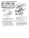
WARNING
DO NOT attempt any maintenance, adjustments or
service with engine and blade running. STOP engine
and blade. Disconnect spark plug wire and secure
away from spark plug. Engine and components are
HOT. Avoid serious burns, allow sufficient time for
all components to cool.
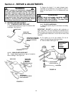
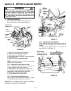
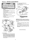
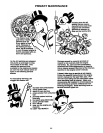
4.3.6. Replacement Of Bearing On Pulley End Of
Hex Shaft
To replace the bearing on the pulley end of the hex
shaft, proceed as follows:
1. Hold the hex shaft with an adjustable wrench
held next to the pulley.
2. Remove the 3/8” hex lock nut which is located
on the outside of the right wheel bracket. See
Figure 4.15.
3. Remove holder, O-ring and bearing.
4. Install new bearing.
5. Carefully install new O-ring over the outside of the
new bearing.
6. Install bearing holder and secure with screws.
7. Install 3/8” hex lock nut.
FIGURE 4.15
4.4. BELT SERVICE
On self-propelled mowers, the engine belt transmits
power from engine to drive disc. The drive disc powers
the poly-v belt which engages the transmission that
powers the rear wheels. Should these belts become
worn, they could cause slippage which would impair
mower performance. The condition of the engine belt
and poly-v belt should be checked after every 25 hours
of mower operation.
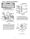
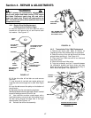
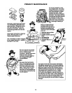
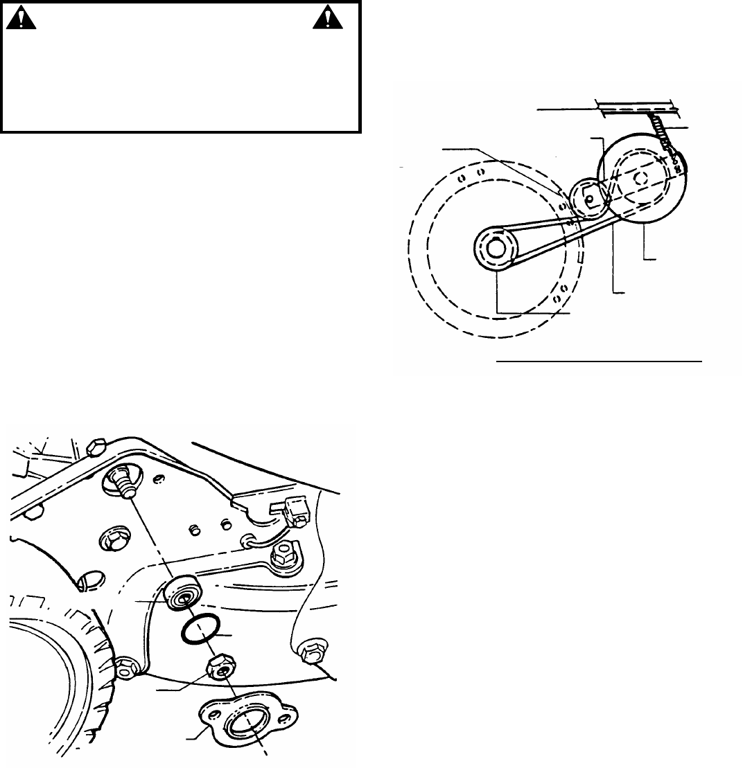
4.4.1. Engine Drive Belt Replacement
1. Empty the fuel tank.
2. Unhook the idler spring from the right rear wheel
bracket. See Figures 4.16.
FIGURE 4.16
IMPORTANT: DO NOT tip machine with carburetor or
spark plug down. Oil from crankcase will saturate the air
filter and cause the engine to be hard to start or not start
at all. If contamination does occur, the air filter will have to
be replaced.
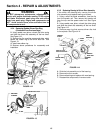
3. Remove the driven disc. Refer to Section
“Replacing Driven Disc Rubber Ring” for driven disc
removal procedure.
4. Do not tilt mower with spark plug or carburetor
down. Tilt mower up on its rear wheels and remove
blade and blade hub. Assistance from another
person may be necessary to hold mower in the
tilted position.
(Continued On Next Page)
BALL BEARING
“O” RING
3/8”
LOCK NUT
BALL BEARING
HOLDER
RIGHT REAR
WHEEL BRACKET
IDLER
ARM
IDLER
SPRING
SLOT IN
DECK
DRIVE DISC
DRIVE BELT
ENGINE DRIVE PULLEY
TOP VIEW OF ENGINE BELT ROUTING