


23
Troubleshooting & Adjustment
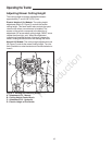
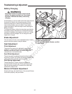
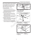
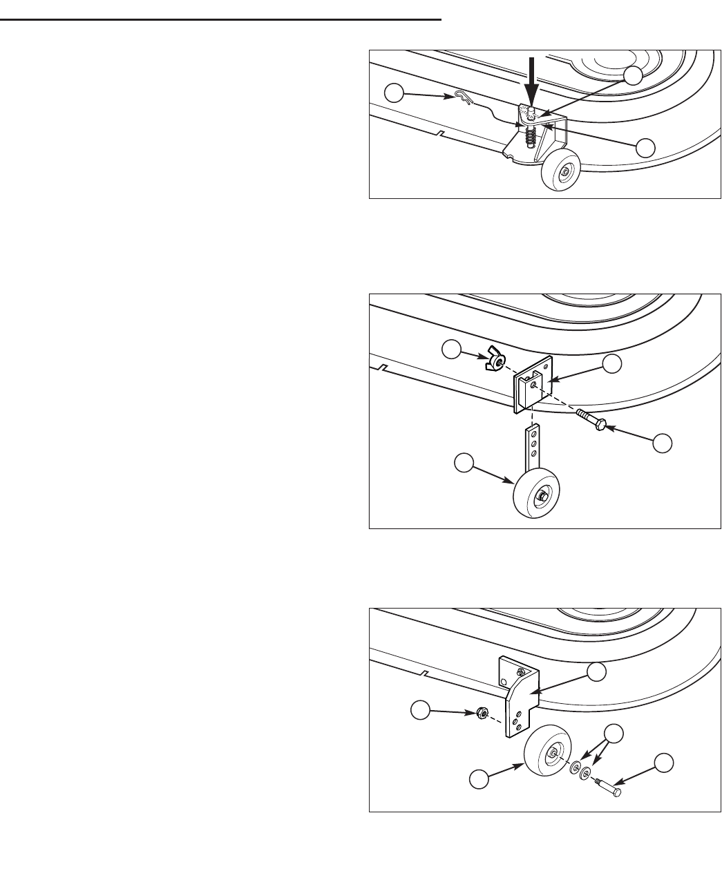
Figure 11. Pivoting Gauge Wheel Adjustment
A. Hair Pin (Upper Position)
B. Hair Pin (Lower Position)
C. Gauge Wheel Bracket
A
B
C
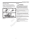
Figure 12. Sliding Bracket Gauge Wheel Adjustment
A. Nylock Wing Nut C. Capscrew
B. Gauge Wheel Bracket D. Gauge Wheel
B
A
C
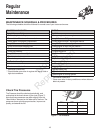
Figure 13. Fixed Bracket Gauge Wheel Adjustment
A. Gauge Wheel Bracket D. Washers
B. Locknut E. Shoulder Bolt
C. Gauge Wheel
A
B
C
D
E
D
Mower Gauge Wheels (Select Models)
The mower gauge wheels can be placed in several
positions depending on the height of cut. When using
higher cutting heights, set the wheels in the lower
position. When using lower cutting heights, set the
wheels in the upper position. To adjust:
PIVOTING GAUGE WHEELS
1. Remove the hair pin clip (A, B, Figure 11).
2. For upper position, install the pin (A) through the
spindle above the bracket (C). For the lower position,
push down on the top of the spindle, and install the
hair pin clip (B) below the top of the bracket (C).
SLIDING BRACKET GAUGE WHEELS
1. Remove the nylock wing nut (A, Figure 12) from
capscrew (C). Slide out capscrew (C) from gauge
wheel bracket (B). Change position of gauge wheel
assembly to desired height.
2. Insert capscrew (C) through gauge wheel bracket (B)
and gauge wheel assembly (D). Tighten nylock wing
nut (A). Repeat Steps 1 & 2 for all gauge wheels.
FIXED BRACKET GAUGE WHEELS
1. Remove the locknut (B, Figure 13), gauge wheel (C),
washers (D), and shoulder bolt (E). Change position
of gauge wheel to desired height.
2. Insert shoulder bolt (E) through washers (D) gauge
wheel (C), and gauge wheel bracket (A). Secure with
locknut (B). Repeat Steps 1 & 2 for all gauge wheels.
Not for
Reproduction