


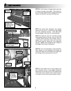
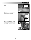
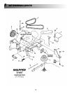

STEP 16: Lay cover assembly on cross assembly.
Align hinges on cross assembly with hinges on
cover, and install one round head pin through each
set of hinge holes, securing with a hair pin.
STEP 17: Slip looped end of cover support cord
onto threaded stud on hose adapter assembly.
Secure end of cord with one 3/16” flat washer and
10-32 nyloc nut (not shown). Run nut all the way in
on thread, but leave cord loose enough to swivel.
3
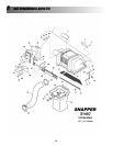
unit assembly
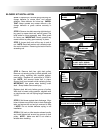
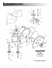
STEP 13: Hook bottom of bagger frame onto pins
in bottom of bumper mount plate. Then slide lock-
ing rod through aligned holes in bagger frame and
bumper mount plate, securing with bridge pin.
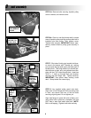
STEP 14: Install cross assembly onto bagger
frame with four 3/8-16 x 3/4 bolts and hex flange
lock nuts, tightening securely. Insert bolts back
through bagger frame and into cross assembly.
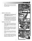
STEP 15: Insert two 5/16-18 x 3/4 bolts through
reinforcement plate (not shown; refer to Parts List
- Catcher Mount Group), then through holes in
bagger frame. Install cover latch arm onto bolts
and secure with hex flange lock nuts, tightening
securely. NOTE: Use the leftmost set of holes in
the bagger frame when installing arm.
8
HOOK BAGGER
FRAME ONTO
BUMPER MOUNT
PLATE PINS
SLIDE ROD
THROUGH
HOLES
INSERT PIN
INTO ROD
CROSS ASSEMBLY
COVER
LATCH
ARM
HINGES
ROUND
HEAD PIN
HAIR PINS
ROUND
HEAD PIN
SLIP CORD
ONTO STUD
AND SECURE
WITH WASHER
& NUT
INSTALL REINFORCEMENT
PLATE ON BACK SIDE OF
BAGGER FRAME