


12
Section 3 - ADJUSTMENTS & REPAIR
3.5.1 TENSION TEST: Start the engine with tiller in
neutral. Shift transmission into FWD & TILL
and pull the wheel and tine control bail up
against the handle bar. Tines and wheels will
start to rotate. Release control bail. Tines and
wheels should stop rotating immediately. If
rotation continues after release of control bail
then clutch spring tension is to great and will
have to be readjusted as described in BELT
TENSION ADJUSTMENT Section.
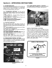
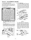
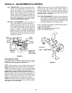
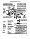
3.5.2 BELT REPLACEMENT: Pull the clevis pin
from the left wheel and slide the wheel out 1”,
remove belt guard and then the old belt.
NOTE: Replacement belt must go over the top
of the idler and be within the belt guide as
shown in Figure 15. Check belt tension as
described in BELT TENSION ADJUSTMENT
Section. Reinstall guard, push left wheel back
into position, secure with clevis pin and insert,
and secure cotter pin.
FIGURE 15
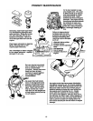
OFF SEASON STORAGE
Thoroughly clean all external surfaces and tines before
storing the Tiller. The Tiller may be stored on end,
however, the following steps must be taken:
STEP 1: Drain gasoline from fuel system and drain the
engine crankcase oil (refer to engine manual for details).
STEP 2: After standing the Tiller on end, check the plugs
in the chain case for leakage. After extended period,
some grease may seep through upper bearing races.
STEP 3: Remove both wheels and grease wheel shafts.
Reinstall wheels. Remove both tines and grease tine
shafts. Reinstall tines. Grease these shafts when tiller is
stored for long periods to prevent rust buildup. Rust
buildup will cause wheels and tines difficult to remove.
STEP 4: At the start of the new season, replenish engine
crank case oil and add gasoline to the fuel tank after
returning the Tiller to its wheels.
STEP 5: Before starting, move the ENGINE CONTROL to
OFF and pull rope starter slowly several times. If
excessive resistance is felt, remove the spark plug and
pull rope starter rapidly to spin the engine and clear oil
from the cylinder. Clean and reinstall spark plug before
attempting to start the engine.
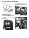
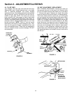
3.5.3 TINE REPLACEMENT: Remove left and right side
plate. Remove shear bolts and nuts that secure the
tine assembly to tine shaft. Remove shoulder bolts and
nuts that secure the tines to tine hub weldment. Install
new tines and tighten nuts and bolts securely.
5-7831 Complete Tine Assembly (Includes Following Items)
4-6798 Tine Hub Weldment
3-8215 Tine 11-1/2” (4)
1-4981 Hex Flange Shoulder Bolt 3/8-24 (8)
9-0524 Hex Lock Nut 3/8-24 (8)
FIGURE 16
Available Kits
6-0731 Hiller/Furrower Kit
6-0865 Cultivator Shield Kit
SHIFT
LEVER
DRIVEN
PULLEY
REMOVE LEFT
HAND WHEEL
& BELT GUARD
BELT
OVER TOP
OF IDLER
DRIVE
PULLEY
BELT
GUIDE