


8
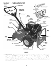
Section 2 - OPERATING INSTRUCTIONS
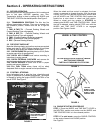
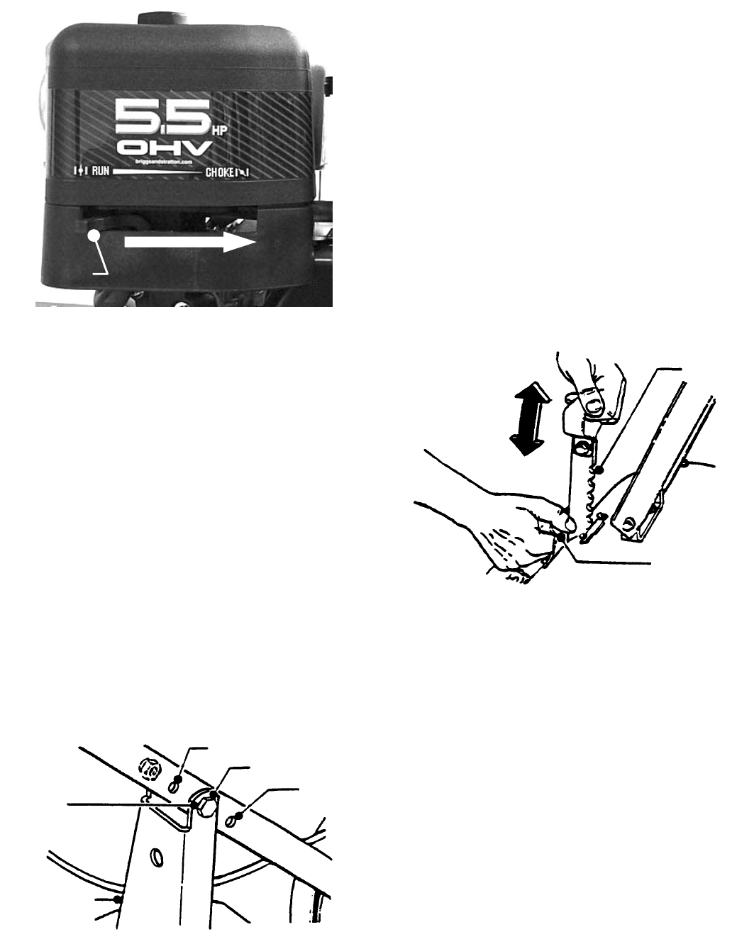
FIGURE 5
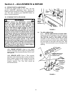
STEP 3: Move ENGINE SPEED CONTROL to FAST
position and turn FUEL VALVE to ON position.
STEP 4: Move to the right side of Tiller and place your foot on
top of the right wheel (See starting procedure decal located on
top of the tine cover), hold handle bar, then pull the ROPE
STARTER HANDLE in smooth, steady motion until the
engine starts. To prolong the life of the rope, guide the handle
back to the engine rather than allowing it to snap back.
STEP 5: Allow a brief warm-up period, then move the
CHOKE CONTROL rearward to RUN POSITION and the
ENGINE SPEED CONTROL to the desired speed setting.
Refer to the tilling procedure column on this page.
STEP 6: To STOP the engine, pull the ENGINE SPEED
CONTROL on engine rearward into STOP position and turn
FUEL VALVE to OFF position.
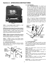
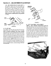
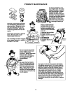
2.5 HANDLE BAR ADJUSTMENT
Remove retaining screw and nut from handle bar bracket.
Adjust handle bar “UP” or “DOWN” as required. Reinstall
screw and nut. See Figure 6.
FIGURE 6
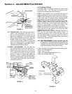
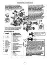
2.6 TRANSPORTING
2.6.1. FORWARD/REVERSE: To transport the
Tiller to a new tilling site using its own power, raise
the tines to clear lawn and paved surfaces to
prevent gouging. Release the WHEEL and TINE
CONTROL BAIL and lift the rear of the Tiller to take
the weight off the DEPTH BAR (see Figure 7), then
push the DEPTH BAR downward into notch setting
that allows the tines to clear the ground surface.
Place the WHEEL and TINE SHIFT LEVER in FWD
or REV. Pull the WHEEL and TINE CONTROL
BAIL back against the handlebar to engage the
wheel drive and transport the unit.
2.6.2. To transport the Tiller to a new tilling site by
pushing it, place the WHEEL and TINE SHIFT
LEVER in the NEUTRAL position, and with the bail
released, push the unit with the handle bar. The
Tiller may be pushed with the engine running or
shut off.
FIGURE 7
2.7 TILLING PROCEDURE
Tines are engaged ONLY when the WHEEL and TINE
SHIFT LEVER is in the FWD & FWD TIL or FWD & REV
TIL position and the WHEEL and TINE CONTROL BAIL is
held against the handle bar.
STEP 1: Set HANDLE BAR in desired position before
beginning operation.
STEP 2: Set DEPTH BAR to desired position. Highest
position is deepest depth. See Figure 7.
STEP 3: Move the ENGINE SPEED CONTROL to
desired setting.
STEP 4: To start TILLING action, move the WHEEL and
TINE SHIFT LEVER to the FWD & FWD TIL or FWD
REV TIL position.
STEP 5: Engage the WHEEL and TINE CONTROL.
Machine will start forward movement and tilling.
IMPORTANT: To STOP forward movement and tine
rotation, release the wheel and tine control.
LOW
MEDIUM
HIGH
REMOVE
SCREW TO
ADJUST
HANDLEBAR
HANDLE
BRACKET
ADJUST UP OR
DOWN TO
DESIRED
TILLING DEPTH
DEEP
TILL
SHALLOW
TILL
PULL SPRING
BACK TO
RELEASE
TENSION
DEPTH
BAR
PUSH FORWARD TO CHOKE
CHOKE
LEVER