


16
Section 4 - REPAIR & ADJUSTMENTS
WARNING
DO NOT attempt any maintenance, adjustments or
service with engine and blade running. STOP
engine and blade. Disconnect spark plug wire and
secure away from spark plug. Engine and
components are HOT. Avoid serious burns, allow
sufficient time for all components to cool.
4.3.4. Replacing Driven Disc Rubber Ring
(Continued From Previous Page)
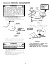
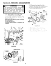
2. Using needle nose pliers, unhook the drive
spring and slide the driven disc assembly off the
hex shaft. See Figure 4.10.
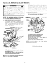
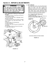
3. Remove the five machine screws and plate
which secure the rubber ring to the driven disc
hub. See Figure 4.11.
4. Install new rubber ring.
5. Reverse above procedures for reassembly and
installation.
FIGURE 4.10
FIGURE 4.11
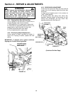
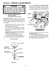
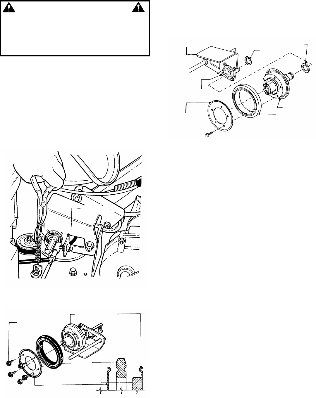
4.3.5. Replacing Bearing In Driven Disc
If the driven disc bearing fails, remove the driven
disc assembly and replace bearing as follows:
1. Remove snap ring. See Figure 4.12.
FIGURE 4.12
2. Slide the hub assembly out of the bearing.
3. Remove the four screws.
4. Remove bearing and replace with new bearing.
5. Reassemble components in reverse order.
SHIM
WASHER
SNAP
RING
THRUST
PLATE
BEARING
REMOVE FOUR
MACHINE SCREWS
DRIVEN DISC
PLATE
DRIVEN
DISC HUB
RUBBER
DISC
MACHINE
SCREWS
DRIVEN DISC HUB
RUBBER
RING
PLATE
DRIVEN DISC
ASSEMBLY