


15
Section 4 - REPAIR & ADJUSTMENTS
WARNING
DO NOT attempt any maintenance, adjustments or
service with engine and blade running. STOP
engine and blade. Disconnect spark plug wire and
secure away from spark plug. Engine and
components are HOT. Avoid serious burns, allow
sufficient time for all components to cool.
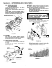
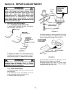
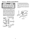
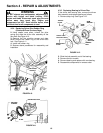
3. Slide driven disc assembly over to 1/8” from
outside edge of drive disc. Maintaining the 1/8”
measurement, remove any misalignment from the
transfer rod linkage and the driven disc assembly
anchor point. This can be done by loosening nut and
rotating the transfer rod ball joint clockwise on the
transfer rod until alignment with the driven disc
assembly anchor point is achieved. Retighten ball
joint nut. Insert ball joint into anchor point and reinstall
the connector hex nut and tighten securely. See
Figure 4.8. Move ground speed control to the first
speed position, then back to the sixth speed position.
Recheck the 1/8” measurement described previously.
Reinstall driven disc spring to driven disc assembly.
FIGURE 4.8
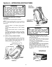
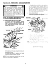
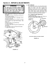
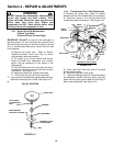
4.3.4. Replacing Driven Disc Rubber Ring
If the rubber ring is badly chunked or worn down to
within 1/16” of the metal rim of the driven disc hub,
it must be replaced. Install new rubber ring as
follows:
1. Using a small flat blade screwdriver, free the
clip from the transfer rod. Then remove the
transfer rod from the clip and the speed control rod.
See Figure 4.9.
FIGURE 4.9
SPEED CONTROL
ROD
CONNECTOR
CLIP
TRANSFER
ROD
1/8” MEASUREMENT TO
OUTSIDE EDGE OF DRIVE
DISC
DRIVE
DISC
OUTSIDE
EDGE
CONNECTOR
HEX NUT
ROTATE BALL JOINT
CLOCKWISE
TRANSFER
ROD
SLIDE DRIVEN
DISC ASSEMBLY
TOWARD
OUTSIDE EDGE