


22
Operating the Tractor
A
B
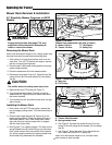
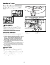
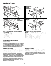
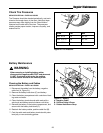
Figure 15. Mower Hitch
A. Tractor Hitch Brackets
B. Spring-Loaded Lever
Removing the Mower Deck
1. Park the tractor, fully lower the attachment lift, turn off
the PTO, turn off the engine, remove the key, and
engage the parking brake. If equipped, pivot the
gauge wheels into sliding position (see Figure 11).
2. Place mower in the lowest cutting position using the
mower height control.
3. Place the attachment lift in the highest position.
4. From left side of tractor, use the idler arm (F, Figure
14) to relieve belt tension. Remove the belt (E) from
the PTO pulley.
5. Disconnect outside chain (D, Figure 14) from hanger
(C). Repeat on other side.
6. Place the attachment lift in the lowest position.
7. Disconnect lift chain (B) from lift hook (A). Repeat on
other side.
8. Turn the wheels straight ahead. Pull back on spring-
loaded lever (B, Figure 15) and lift mower hitch off of
the tractor brackets (A).
9. Turn wheels fully left, and slide mower deck out from
under the right side of the tractor.
Installing the Mower Deck
NOTE: Perform mower installation on a hard, level sur-
face such as a concrete floor.
1. Park the tractor, fully lower the attachment lift, turn off
the PTO switch, turn off the engine, remove the key,
and engage the parking brake. Turn the wheels fully
to the left.
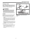
WARNING
Engage parking brake, disengage PTO, stop
engine and remove key before attempting to
install or remove the mower.
Muffler and surrounding areas may be hot.
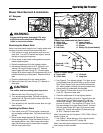
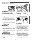
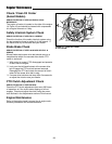
Figure 14. Mower Lift
A. Lift Hook D. Outside Chain
B. Lift Chain, Inside E. PTO Belt
C. Hanger F. Idler Arm
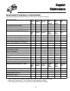
Mower Deck Removal & Installation
50” Snapper Models
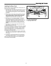
2. Place mower in the lowest cutting position using the
mower height adjuster. Slide the mower deck under
the right side of tractor so that the mower hitch is
aligned with front tractor hitch (A, Figure 15).
3. See Figure 15. Turn wheels straight. Pull back on
the spring-loaded lever (B) while lifting up on the
mower hitch. Install the mower hitch onto tractor hitch
brackets (A). When properly installed, the spring-
loaded lever should seat fully underneath the brack-
ets (A).
4. Connect the lift chains (B, Figure 14) to the the trac-
tor lift hooks (A).
5. Place the attachment lift in the highest position.
6. Connect outside chains (D, Figure 14) to hanger (C).
7. From left side of tractor, use the idler arm (F, Figure
14) to relieve belt tension. Install belt (E) onto the
PTO pulley.
8. If equipped, raise the attachment lift and rotate the
front gauge wheels (Figure 11) into cutting position.
C
D
F
B
A
E
CAUTION
The muffler and surrounding areas may be hot.