


10
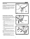
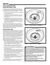
Engine Controls
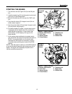
STARTING CONTROLS
See Figures 1 & 2 for the following instructions.
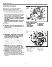
Units with Optional Electric Start
A. Electric Start Button (North American Models)-
The electric start button (A) activates an electric
starter mounted to the engine, eliminating the need to
pull the starter handle. The electric start button oper-
ates on 120 Volts AC, which is provided by connec-
tion to the extension cord provided with units
equipped with this feature.
Connect this extension
cord ONLY to a properly grounded 3 prong elec-
trical outlet.
Electric Start Button (CE Models)- Please refer to
the detailed instructions supplied with the electric
start kit.
Manual Start
B. Fuel Valve - The fuel valve (B) is located under the
fuel tank. It is used to turn the fuel supply off for out-
of-season storage.
C. Starter Handle - The starter handle (C) connects to a
starter cord to manually start the engine. Pulling
starter handle rapidly spins the engine crankshaft,
cycles the engine, and generates the spark neces-
sary for starting the engine.
D. Primer Button - When pressed, the primer button
(D) provides initial fuel to help start a cold engine.
Normally, pressing the primer button twice will pro-
vide enough fuel to start a cold engine.
E. Throttle Lever - The throttle lever (E) controls the
engine speed. For best overall performance, the
throttle lever should be set to the FAST position. Use
the SLOW position only for warming the engine, or to
help prevent snow/ice freeze-up when shutting the
unit down for the day.
F. Engine Key - The engine key (F) prevents the
engine from being started by unauthorized individu-
als. The key must be fully inserted into the key slot
for the unit to start. The key is also used to stop the
engine by pulling the key out of the key slot.
G. Choke Knob - The choke knob (G) adjusts the
air/fuel mixture, and is used to help start a cold
engine by providing a richer mixture. Once the engine
is warm and running smoothly, the choke knob
should be set to the off position to provide a normal
air/fuel mix.
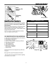
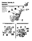
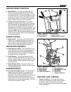
Figures 2. Engine Controls
A. Electric Start Button E. Throttle Lever
B. Fuel Valve F. Engine Key
C. Starter Handle G. Choke Knob
D. Primer Button
B
A
C
D
E
F
G
C
D
E
F
B
G
A
Tecumseh
L-Head
Models
Briggs &
Stratton OHV
Models
Figures 1. Engine Controls
A. Electric Start Button E. Throttle Lever
B. Fuel Valve F. Engine Key
C. Starter Handle G. Choke Knob
D. Primer Button