


Instruction Manual No. 7102356 (Rev. C, 06/04/2008)
TP 200-5352-C-AT-N
3
Installation Instructions
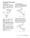
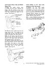
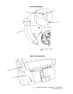
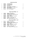
Install Bagger Mount
1) Remove three bolts – two on the rear
of the tractor frame, and the top bolt on
the right rear of the tractor frame. See
Figure 1. The two rear bolts will be
replaced with longer bolts supplied in
the kit. Save the right bolt for re-
installation.
2) Align the holes in the Bagger Mount
Weldment (P/N 7400272A) with the
holes in the tractor frame.
3) Install one bolt 1/2-13x1-1/4
(7091323, not shown) into the hole in
the lower bagger mount and the tractor
frame (‘hitch mount’ hole). See Figure
1. Secure with one hex nut 1/2-13
(7091544). Do not tighten hardware at
this time.
4) Install two bolts 5/16-18x1-1/4
(1930595) into the rear of the tractor
frame. These replace the two removed
in Step 1. Secure with two flange hex
nuts 5/16-18 (1927557). Also, re-install
the right bolt into the right rear of the
tractor frame.
5) Tighten all hardware securely.
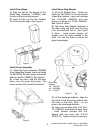
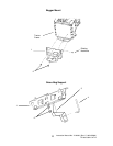
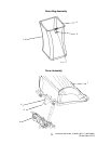
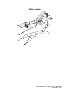
Install Grass Bag Support
1) Align the lower U-shaped channel on the
Grass Bag Support (7500994) with the U-
shaped slot in the top of the Bagger Mount.
Insert the channel support fully into the
bagger mount. See Figure 2.
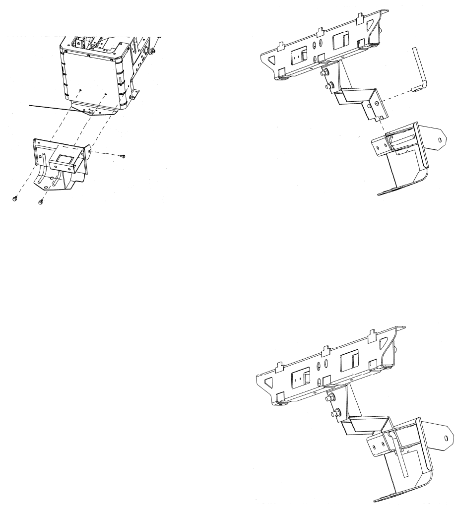
2) Secure the Grass Bag Support to
the Bagger Mount with the Mounting Pin
(M720527). Hold the pin with the leg
up. Insert the Mounting pin fully into the
Bagger Mount. Rotate the mounting pin
so that the leg will be pointing down,
locking the pin in place. See Figure 3.
Figure 1
Figure 2
Figure 3
‘Hitch
Mount’
hole