


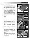
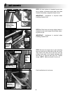
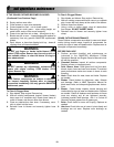
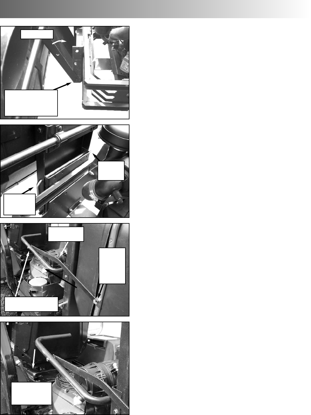
STEP 15: Hook the large hole of each actuating
arm onto the hook on each side of the rear cover.
Then secure the other end of the arm onto the
inside of each side of the handle weldment with
one 3/8-16 x 2” hex bolt and nyloc nut. Tighten
snugly. NOTE: Make sure bend of arm is up.
Push handle down to lock cover.
3
unit assembly
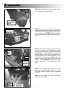
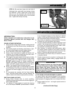
STEP 13: Hook bottom of clamshell mount onto
pins in bottom of bumper mount plate, then raise
clamshell assembly up against bumper mount.
IMPORTANT: Assistance is required when
installing clamshell unit.
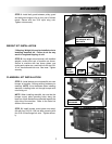
STEP 14: Slide hitch rod through aligned holes in
clamshell mount and bumper mount plate, secur-
ing with hair pin.
IMPORTANT: Assistance is required when
installing clamshell unit.
8
HOOK CLAMSHELL
MOUNT ONTO
BUMPER MOUNT
PLATE PINS
RAISE UNIT
SECURE
WITH
HAIR PIN
BOLT ARM TO
INSIDE OF HANDLE
HOOK
LARGE
HOLE OF
ARM
HERE
PUSH HANDLE
DOWN TO
LOCK COVER
SLIDE ROD
THROUGH
HOLES
MAKE SURE
BEND IS UP