


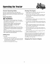

OperatiflgtheTractor
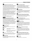
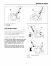
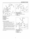
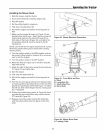
Figure 12. Install Sway Arms
A. Sway Arms
B. Hair Pin Clips
C. Clevis Pins
D. Upper Link Assembly
E. Safety Clips
F. Clevis Pins
Hitch Arms Installation
1. Attach the upper lift link (D, Figure 12) to the hitch
using a clevis pin (F) and safety clip (E).
2. Attach the sway arms (A, Figure 12) to the hitch
assembly using clevis pins (C) and hair pin clips (B).
The arms should angle out, away from center.
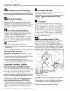
3. Attach the sway chains (D, Figure 13) to the back of
the sway arms (A, E) using 3/8 x 1-1/2 capscrews (C)
and 3/8 Iocknuts. Cross the chains and secure to
front of the sway arms with clevis pins and hair pin
clips (B).
4. Attach the adjustable link (E, Figure 14) and lift link
assembly (C) using clevis pins (B) and hair pin clips.
NOTE: The adjustable lower lift link (E, Figure 14) goes
on the right side.
Figure 13. Install Chains
A. Right Sway Arm
B. Clevis Pin & Safety Clip
C. Capscrew, 3/8-16 x 1-1/2 & Locknut
D. Chains
E. Left Sway Arm
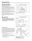
Figure 14. Install Lift Links
A. Left Sway Arm
B. Clevis Pin & Hair Pin Clip
C. Fixed Lift Link
D. Lift Lever
E. Adjustable Lift Link
19