


OperatiflgtheTractor
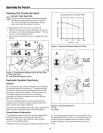
Pushing The Tractor By Hand
DO NOT TOW TRACTOR
Q Towing the unit will transmission
cause
damage.
Do not use another vehicle to push or pull this
unit. Do not actuate the transmission release
valve lever while the engine is running.
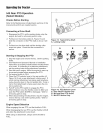
1. Disengage the PTO and turn the engine off.
2. Push the transmission release (B, Figure 4) forward
and down to lock into the released position. The trac-
tor can now be pushed by hand.
3. Move the lever rearward and up to engage the trans-
mission.
O
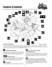
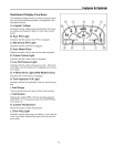
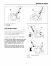
Figure 4. Transmission Release Lever & Fuel Tank
A. Fuel Tank Cap.
B. Transmission Release Lever
Hydraulic System Functions
General
All of the inboard and auxiliary hydraulics are controlled
by the attachment lift control lever. The attachment lift
control lever raises and lowers attachments that utilize
the tractor's hydraulic lift cylinder. This lever also con-
trols attachments that use the tractor's auxiliary
hydraulics via the quick couplers on the front left and
right sides of the frame.
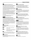
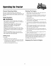
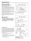
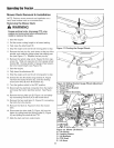
The rate of hydraulic fluid flow and pressure that are
available when using the auxiliary hydraulic quick cou-
plers is listed in the chart in Figure 5.
The lever has five positions: left, right, back, forward (first
detent) and float (pushed forward to second detent).
Using Inboard Hydraulics
The inboard hydraulics control the tractor's belly attach=
ment lift (mower deck) and three point hitch lift (if
equipped). The front / rear hydraulic selector switch
must be in the REAR position.
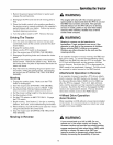
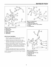
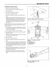
Pulling the lever back raises the attachment lift (A, Figure
E
CL
Ob
I
©
LL
E
q3
CL
_E
7,
6.
5.
Implement Flow @ 3600 RPM
100 200 300
Pressure -- psi
400
Figure 5. Hydraulic System Pressure / Flow
AI
BI
Figure 6. Inboard Hydraulics
A. Lift
B. Lower
6). Pushing the lever forward to the first detent lowers
the attachment lift (B, Figure 6). Pushing the lever for-
ward to the second detent locks the control in "float"
position, allowing the lift mechanism to float up and
down.
16