


Section 4 - REPAIR & ADJUSTMENTS
WARNING
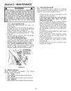
DO NOT attempt any maintenance, adjustments or
servicewith engine and blade running.STOP engine
and blade.Disconnect spark plug wire and secure
away from spark plug. Engine and components are
HOT. Avoid serious burns,allow sufficienttime for
allcomponents to cool.
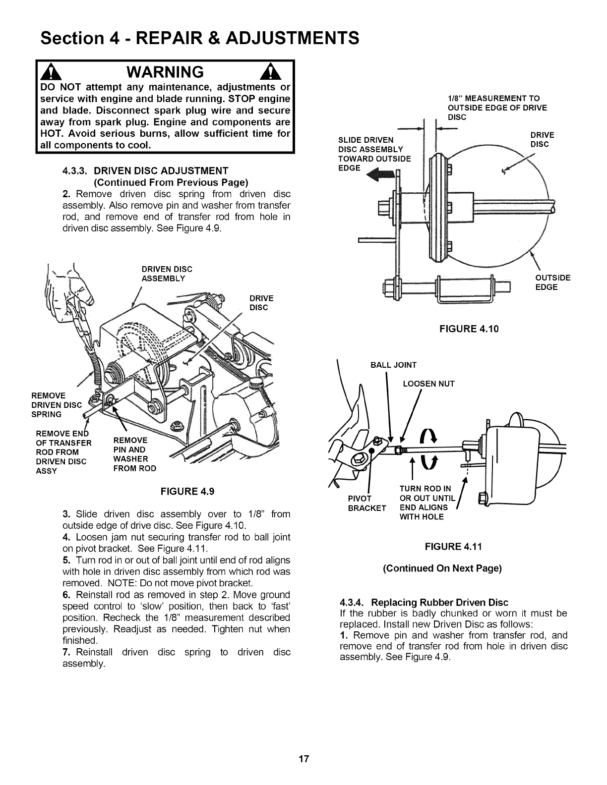
4.3.3. DRIVEN DISC ADJUSTMENT
(Continued From Previous Page)
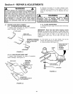
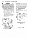
2. Remove driven disc spring from driven disc
assembly. Also remove pin and washer from transfer
rod, and remove end of transfer rod from hole in
driven disc assembly. See Figure 4.9.
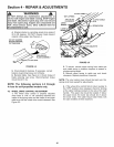
DRIVEN DISC
ASSEMBLY
DRIVE
DISC
SLIDE DRIVEN
DISC ASSEMBLY
TOWARD OUTSIDE
EDGE
1/8" MEASUREMENT TO
OUTSIDE EDGE OF DRIVE
DISC
DRIVE
DISC
OUTSIDE
EDGE
FIGURE 4.10
REMOVE
DRIVEN DISC
SPRING
REMOVE END
OF TRANSFER REMOVE
ROD FROM PIN AND
DRIVEN DISC WASHER
ASSY FROM ROD
FIGURE 4.9
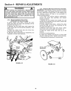
3. Slide driven disc assembly over to 1/8" from
outside edge of drive disc. See Figure 4.10.
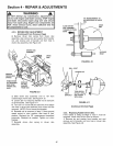
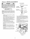
4. Loosen jam nut securing transfer rod to ball joint
on pivot bracket. See Figure 4.11.
5. Turn rod inor out of ball joint until end of rod aligns
with hole in driven disc assembly from which rod was
removed. NOTE: Do not move pivot bracket.
6. Reinstall rod as removed in step 2. Move ground
speed control to 'slow' position, then back to 'fast'
position. Recheck the 1/8" measurement described
previously. Readjust as needed. Tighten nut when
finished.
7. Reinstall driven disc spring to driven disc
assembly.
BALL JOINT
LOOSEN NUT
PIVOT
BRACKET
TU .:
TURN ROD IN /
OR OUT UNTIL/
END ALIGNS !
WITH HOLE
FIGURE 4.11
(Continued On Next Page)
4.3.4. Replacing Rubber Driven Disc
If the rubber is badly chunked or worn it must be
replaced. Install new Driven Disc as follows:
1. Remove pin and washer from transfer rod, and
remove end of transfer rod from hole in driven disc
assembly. See Figure 4.9.
17