


7
Channel Installation
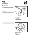
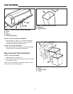
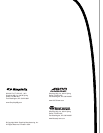
Figure 8. Install Channel Assembly
A. Channel Assembly
B. Hitch
C. Pin
C
B
INSTALL CHANNEL ASSEMBLY AND “U”-TUBE
1. Slide the channel assembly (A, Figure 8) into hitch
(B) as shown.
2. Install the pin (C) into the right side of hitch (B) and
turn pin (C) counterclockwise to lock in place.
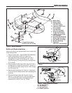
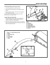
3. Install the “L” channel (E, Figure 9) and “U” tube (A)
to channel assembly (B) as shown. Secure with
5/16-18 x 1-3/4 carriage bolts (C), saddle clamps (F),
and 5/16-18 nuts (D).
4. Install 5/16-18 x 3/4 capscrew (G) and 5/16-18
locknut (D) as shown.
A
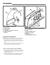
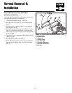
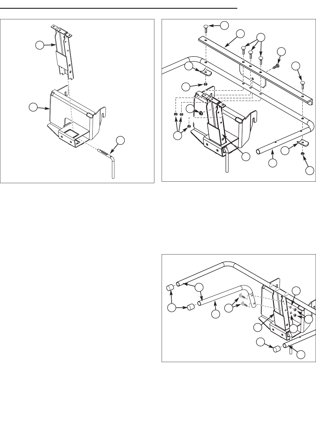
INSTALL TUBES AND END PLUGS
1. Install the center tube (A, Figure 10) to RH side of
channel assembly (B) as shown. Secure with 5/16-
24 screws, 5/16 lockwashers (C) and 5/16-24 nuts
(D).
2. Install the end caps (G) to tube ends (F) as shown.
A
D
C
D
C
C
F
D
F
D
Figure 9. Install “U” Tube
A. “U” Tube
B. Channel Assembly
C. Carriage Bolts, 5/16-18 x 1-3/4
D. Nuts, Nylock, 5/16-18
E. “L” Channel
F. Saddle Brackets
G. Capscrew, 5/16-18 x 3/4
G
E
B
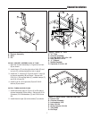
Figure 10. Install Center Tube and End Caps
A. Center Tube
B. Channel Assembly
C. Lockwashers, 5/16
D. Nuts, 5/16-24
E. Screw, Special, 5/16-24
F. Tube Ends
G. End Caps
F
G
F
G
E
D
C
C
A
B