


13
Initial Setup & Assembly
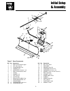
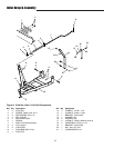
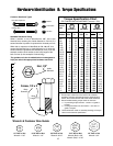
Figure 13. Control Rod Support
A. Angling Support D. 5/16 Flatwasher
B. Eyebolt & Locknut E. Flange Locknuts
C. 5/16-18 x 1-1/2 Capscrews
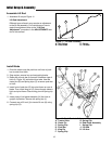
Install Angling Control Rod
NOTE: If installing the dozer attachment on a unit
equipped with a snowcab, replace the control rod sup-
port (A, Figure 13) with the hanging support (Ref. No. 19,
Figure 8). Mount the hanging support to the front cab
cross-bar.
1. Set the angling control support (A, Figure 13) against
the right side of the frame. Insert two 5/16-18 x 1-1/2
capscrews (C) through the support (A), and frame.
Space the lower hole away from the frame with a
5/16 washer (D). Secure using flange locknuts (E).
2. Install the eyebolt (B) in the support (A) and secure
with a centerlock nut.
A
B
C
D
E
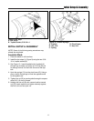
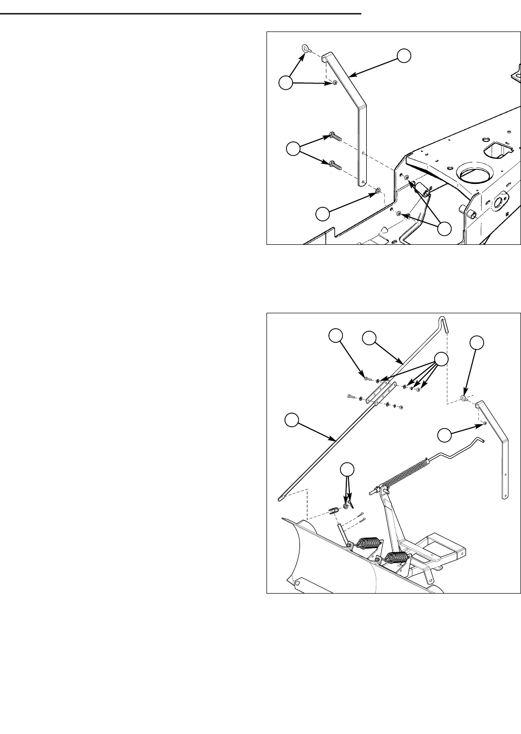
Figure 14. Assemble Control Rods
A. 1/4-20 Centerlock Nut
B. Eyelet
C. Upper Control Rod
D. 5/16-18 x 1-1/4 Capscrew
E. 5/16 Washers, Lockwashers, & Nuts
F. Lower Control Rod
G. Hair Pin Clip & Washer
A
B
C
D
F
G
E
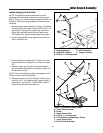
3. Connect the lower angling rod (F, Figure 14) to the
dozer release lever using a hair pin clip and washer
(G).
4. Insert the upper control rod (C) through the eyelet
(B), and secure the eyelet to the support using a 1/4-
20 centerlock nut (A).
NOTE: It may be necessary to leave the eyebolt nut (A,
Figure 14) loose to prevent binding.
5. Secure the upper rod (C) to the lower rod (F) using
two 5/16-18 x 1-1/4 capscrews (D), washers (qty. 4),
lockwashers, and nuts (E). NOTE: Match offset to
offset so the rods form a straight line.