


5
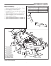
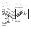
Tube Component Assembly
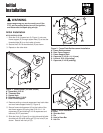
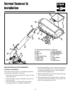
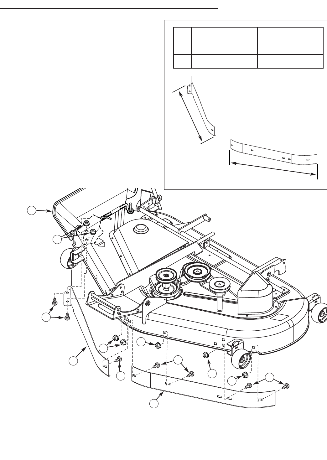
Baffle Installation
1. Determine which baffle to use. See Figure 4 Chart.
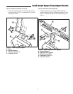
2. Lift side discharge chute (H, Figure 4).
3. Insert baffle (F) through discharge opening and posi-
tion baffle into place.
4. Tighten carriage bolts (A) and nuts (E) on baffle (F).
5. Tighten carriage bolt (B) and nut (E) on baffle (F).
6. Position baffle (G) into place.
7. Tighten carriage bolts (C) and nuts (E) on baffle (G).
8. Tighten carriage bolts (D) and nuts (E) on baffle (G).
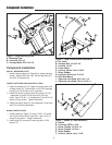
Figure 4. Baffle Assembly
A. Carriage Bolts,
5/16-18 x 5/8
B. Carriage Bolt,
5/16-18 x 5/8
C. Carriage Bolts,
5/16-18 x 5/8
D. Carriage Bolts,
5/16-18 x 5/8
E. Locknut, 5/16-18
F. Right Hand Baffle
G. Left Hand Baffle
H. Discharge Chute
E
A
F
E
E
C
E
E
D
B
G
H
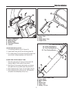
“A”
44” Mower Deck 50” Mower Deck
“A” RH side 26-1/4” long RH side 29-3/4” long
“B” LH side 24-7/8” long LH side 27-3/4” long
“B”