


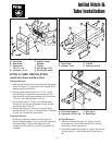

Initial Hitch & Tube Installation
12
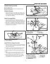
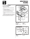
Figure 5. Assemble Tubes & Deflector
A
E
C
F
B
A. Upper Tube
B. Middle Tube
C. Lower Tube
D. Nut, Nylock, 10-24 x 3/4
E. Washer, #10
F. Screw, Truss Head, 10-24
G. Holes
H. Clip and Hardware
Assemble Tubes & Deflector
1. Insert the lower tube (C, Figure 5) into middle tube
(B). Secure the tubes as shown in Figure 5 using
#10-24 x 3/4 screws (F), washer (E) and #10-24 nuts
(D). Insert middle tube (B) into upper tube (A).
Secure the tubes as shown in Figure 5 using #10-24
x 3/4 screws (F)`, washer (E) and #10-24 nuts (D).
2. Place upper tube into catcher opening. Secure the
elbow to the turbo using clip (H).
Note: Relocation of clip and hardware (H) to holes (G)
may be necessary to ensure proper fit. Use correct hole
locations to maintain proper tube connections and pre-
vent lower tube from disconnecting from the turbo.
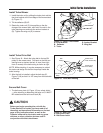
Assemble Catcher Bags
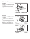
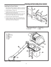
1. See Figure 6. Insert the wire hoop (H) through the
cloth bag (B).
2. Install the clamp (E) and hanger bracket (D). Secure
with two 5/16-18 x 3/4 carriage bolts (C), lockwashers
(G) and nuts (F).
Figure 6. Assemble Catcher Bags
A. Clip E. Clamp
B. Cloth Bag F. Nut
C. 5/16-18 x 3/4 Carriage Bolt G. Lockwasher
D. Hanger Bracket H. Wire Hoop
A
B
C
D
E
F
G
H
D
E
F
D
G
H
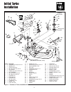
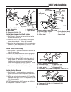
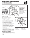
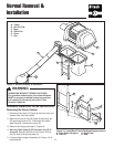
Figure 4. Install Back Plate (Flat Style Bumper shown)
A. Back Plate and Support C. Hitch Plate
B. Hair Pin D. Rod
B
A
D
C