


7
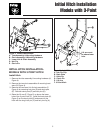
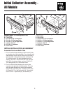
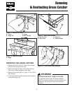
Initial Installation & Assembly
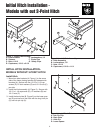
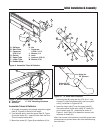
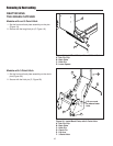
Figure 8. Assemble Tubes & Deflector
A
B
G
G
C
D
E
I
I
J
J
K
J
H
H
L
K
K
J
M
J
A. Deflector
B. Back Plate
C. Capscrew,
5/16-18 x 1
D. Socket
E. Upper Tube
F. Lower Tube
G. Rubber Strap
H. Nut
I. Capscrew,
1/4-20 x 1-1/4
J. Washer, 1/4
K. Hook
L. Locknut, 5/16-18
M. Washer, 5/16
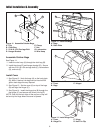
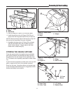
A
Figure 9. Mount Deflector and Tube Pivot
A. Tube Pivot C. 5/16” Mounting Hardware
B. Deflector
B
C
Assemble Tubes & Deflector
1. All models covered by this manual require the upper
tube (E, Figure 8) to be left at full length.
2. If not already done, insert the upper tube (E, Figure
8) into the socket (D). Insert the tube from the front.
This will require some effort.
3. Mount the socket (D, Figure 8) and deflector (A) to
Figure 10. “S” Hook Hole Locations
the back plate (B) using the four 5/16-18 x 1” cap-
screws (C), eight flat washers (M), and four nylock
nuts (L) as shown in Figures 8 & 9.
4. Insert the lower tube (F) into the upper tube (E).
Secure the elbow to the turbo using “S” hooks (K)
and a rubber strap (G). Assemble as shown in
Figure 8. Use Figure 10 to determine correct hole
locations for hooks (K).
Note: Use correct hole locations to maintain proper tube
connections and prevent lower tube from disconnecting
from the turbo.
F
J
H
Holes for 48”
& 60” Mowers
Holes for
54” Mowers