


6
INITIAL INSTALLATION & ASSEMBLY
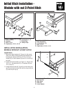
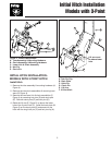
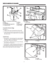
Assemble Front and Back Plate
1. For units with left side discharge use the set of holes
on the right side of the back plate. For units with right
side discharge use the set of holes on the left side of
the back plate. Attach the back plate (A, Figure 6 &
7) to the front plate (B) using carriage bolts, lock-
washers, and nuts. Use two 5/16-18 x 3/4” carriage
bolts (D) in the top two holes, and two 5/16-18 x 1-
1/4” carriage bolts (E) in the bottom holes.
2. For units with left side discharge the cover plate
mounts to the right side of the back plate. For units
with right side discharge the cover plate mounts to
the left side of the back plate. Install the cover plate
(H, Figure 6 & 7) on the back plate (A). Secure with
four 5/16-18 x 1 capscrews (G), and locknuts (F).
A
B
E
F
H
G
E
D
C
Figure 7. Install RH Discharge Back Plate
A. Back Plate
B. Front Plate
C. 5/16-18 Nuts & Lockwashers
D. 5/16-18 x 3/4 Carriage Bolts
E. 5/16-18 x 1-1/4 Carriage Bolts
F. Locknut, 5/16-18
G. 5/16-18 x 1 Capscrew
H. Cover Plate
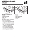
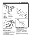
Initial Collector Assembly -
All Models
A
B
E
F
H
G
E
D
C
Figure 6. Install LH Discharge Back Plate
A. Back Plate
B. Front Plate
C. 5/16-18 Nuts & Lockwashers
D. 5/16-18 x 3/4 Carriage Bolts
E. 5/16-18 x 1-1/4 Carriage Bolts
F. Locknut, 5/16-18
G. 5/16-18 x 1 Capscrew
H. Cover Plate