12
Initial Setup & Assembly
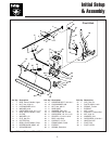
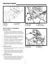
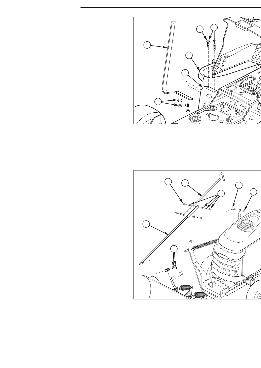
Figure 13. Control Rod Support
A. Support
B. Capscrew, 5/16-18 x 1
C. Washer & Nut
D. Footrest Support (Frame)
E. Foot Rest (Tunnel)
F. Original Taptite Screw (Discard)
Install Angling Control Rod
NOTE: If installing dozer blade on the unit equipped with
a snowcab, the angling rod support (A, Figure 14) is not
required.
1. Remove the front two ratchet fasteners from the right
foot rest pad. Peel the foot rest pad back.
2. Remove and discard the taptite screw (F).
3. Mount the angling control rod support (A) to the bot-
tom of the frame foot rest support (D). Secure using
two 1/16-18 x 1 capscrews, washers, and nuts (C).
NOTE: The inside hole used with the inside capscrew (B)
can be accessed through the gap between the foot rest
(E) and dashboard in front of the brake pedal.
4. Reinstall the foot rest pad.
A
F
E
D
B
C
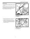
Figure 14. Assemble Control Rods
A. 1/4-20 Nylock Nut
B. Eyelet
C. Upper Control Rod
D. 5/16-18 x 1-1/4 Capscrew
E. 5/16 Washers, Lockwashers, & Nuts
F. Lower Control Rod
G. Hair Pin Clip & Washer
A
B
C
D
F
G
E
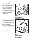
3. Connect the lower angling rod (F, Figure 15) to the
dozer release lever using a hair pin clip and washer
(G).
4. Insert the upper control rod (C) through the eyelet
(B), and secure the eyelet to the support using a 1/4-
20 nylock nut (A).
NOTE: It may be necessary to leave the eyelet nut (A,
Figure 24) loose to prevent binding.
5 Secure the upper rod (C) to the lower rod (F) using
two 5/16-18 x 1-1/4 capscrews (D), washers (qty. 4),
lockwashers, and nuts (E). NOTE: Match offset to
offset so the rods form a straight line.
Downward Pressure Lock
Install the down-pressure lock plate (hydraulic lift mod-
els) or switch the lift bar from mowing position to dozer
position. See page 14.


