


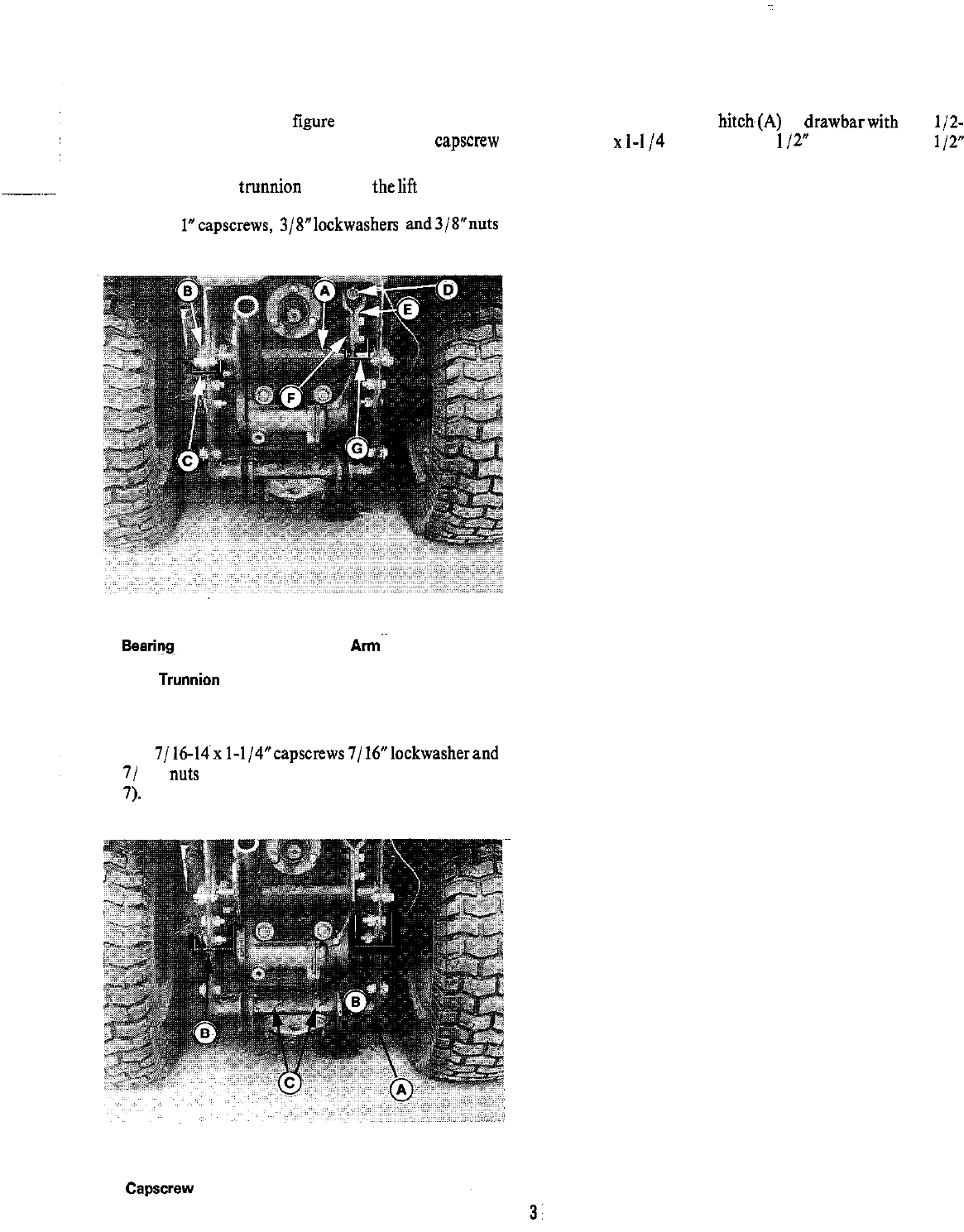
4. Insert the lift shaft (A, figure 8) into position, place
bearing (B) on to each end, and secure with capscrew
lockwasher and nut (C) on each side.
5. Position the rear tnmnion (D) onto
thelift
rod. Install
the lift arm half(E) to lift shaft(F) and secure with two
3/8-16x
l”capscrews, 3/8”lockwashers and3/8”nuts
(G). Install centerlock nut on end of lift rod.
7. From top, connect hitch~(A) to drawbarwith two
l/Z-
13
x
1-I
/4
capscrews (C),
1
/Z” lockwashers, and
l/2”
nuts.
8. Reinstall panels and cover removed in step 1.
Figure 8.
A. Lift Shaft
S.
Searing~~
C. Mtg. Hardware
D. Rear Trunnion
E. Lift
A&
F. Lift Shaft
G. Mtg. Hardware
6. Position the hitch (A, figure 9) as shown and install
two 7/M-14~~ I-1/4”capscrews7/ 16”lockwasherand
7/ 16”
nuts
(B) each side. See mounting holes (B, figure
7).
Figure 9.
A. Hitch
S. Mtg. Hardware
c. Capscrew