


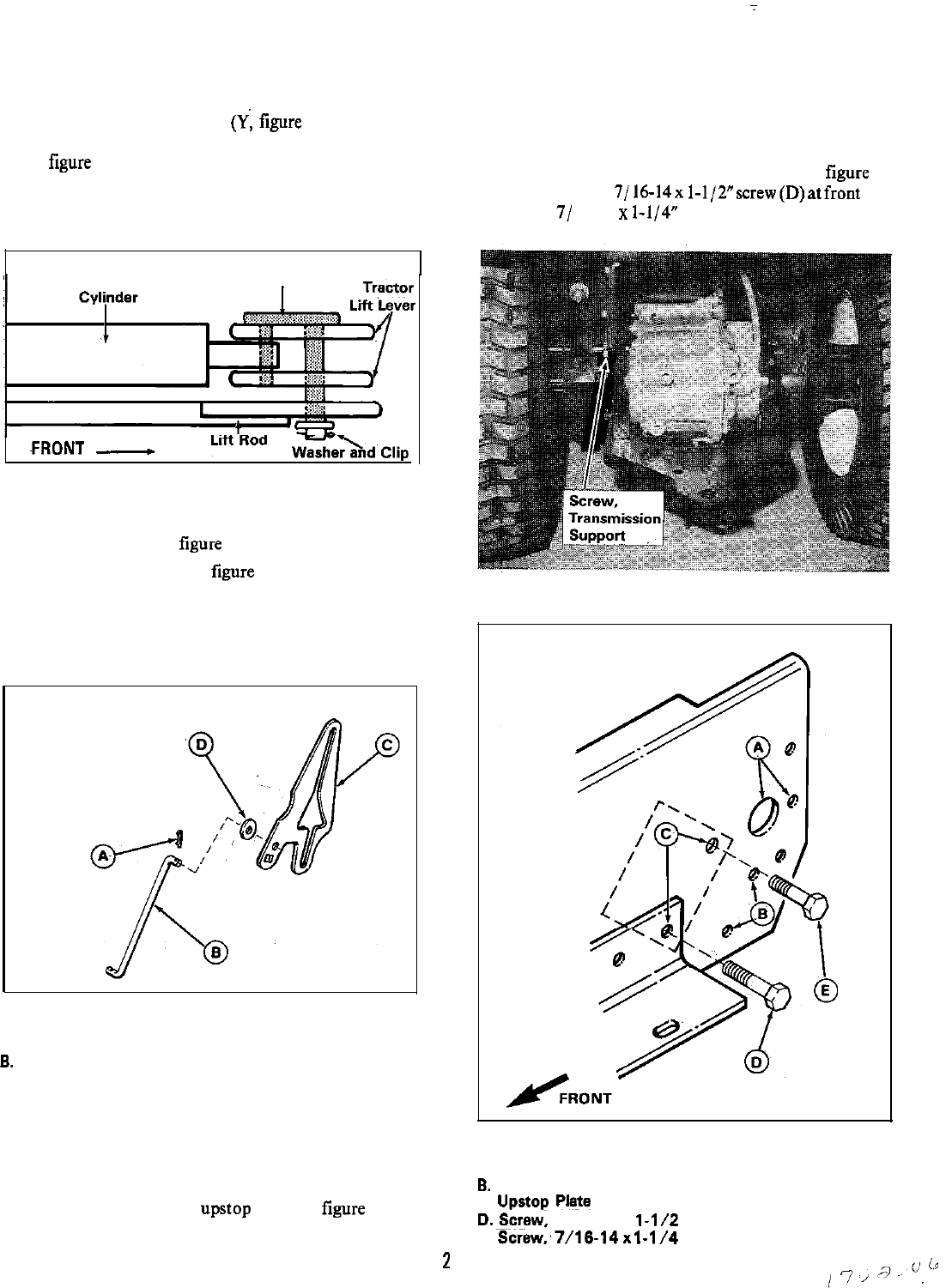
g. Using the front trunnion
(Y;
figure I), connect the
cylinder and lift rod(G) to the tractor lift lever. (See
figure
4.) Position cylinder and insert short leg of
trunnion through it. Connect lift rod to long leg of
trunnion. Be sure lift rod is positioned with flat side
as shown.
VIEWED FROM TOP
~FRONT
-
Figure 4.
2. For 18 hp models, Mfg. No. 1691307, and older, install
special washer (CC,
figure 1) as follows:
a.
Remove cotter pin (A, figure 5) and remove ground
speed control rod (B) from cam plate (C).
b. Install special washer (D) on control rod (B).
Reinstall rod to cam plate and secure with cotter
pin.
Figure 5. Special Washer Installation
A. Cotter Pin
6.
Ground Speed Control Rod
C. Cam Plate
D. Special Washer
3.
If a rear PTO has been installed on the tractor, it is not
necessary to install the
upstop plate (0, figure 1). To
install, proceed as follows:
a. Remove and discard the rear-most screw from the
transmission support (figure 6).
b. Install the plate in mounting holes (C,
figure 7)
shown. Use 7/16-14x 1-1/2”screw(D)atfront hole
and 7/ 16-14
x
l-l/4”
screw (E) at rear hole. Install
lockwashers and nuts.
Figure 6.
VIEWED FROM LEFT SIDE
Figure 7.
A. Lift Shaft Mtg. Holes
6.
Hitch Mtg. Holes
C. Upstop
b’late
Mtg. Holes
D.~sSrwv,
7/16-14x
l-l/Z
E. Screw;7/16-14x
l-1/4
2