


4
Installation Instructions Tube and Latch Kit
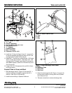
8. Install the “U” tube (A, Figure 9) and “L” channel (F)
to channel assembly (B) securing with 5/16-18 x 3/4
carriage bolts (C) and 5/16-24 nuts (E).
9. Using the “L” channel as a guide drill two 11/32 holes
(G) in “U” tube (A) as shown. Install 5/16-18 x 1-3/4
carriage bolts (C) through new holes (G) and secure
with saddle clamps (F) and 5/16-18 locknuts (D) and
5/16-18 nuts (E).
10. Install 5/16-18 x 3/4 capscrew (H) and 5/16-18 lock-
nut (D) as shown.
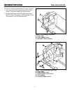
Connect Tube to Cover and Boot
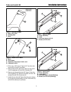
1. Slide discharge tube (A, Figure 10) into seal (B). It
may be necessary to lengthen several slits (C) in
order for tube (A) to fit into seal (B)
2. Install boot according to Operator’s Manual.
A
D
C
D
C
C
F
D
F
D
Figure 9. Install “U” Tube
A. “U” Tube
B. Channel Assembly
C. Carriage Bolts, 5/16-18 X 1-3/4
D. Nuts, Nyloc, 5/16-18
E. “L” Channel
F. Saddle Brackets
G. New 11/32 Holes
H. Capscrew, 5/16-18 x 3/4
Figure 11. Install Discharge Tube to Boot
A. Boot
B. Discharge Tube
C. Metal Puck
D. Wire Form
Figure 10. Install Tube in Cover
A. Tube
B. Seal
C. Slits
A
B
C
H
E
B
G
G
A
D
C
B
Form No. 1733418-01
Rev. 5/2006
© 2006 Simplicity Manufacturing, Inc. All Rights Reserved
TP 200-4298-01-SK-SMA
MANUFACTURING, INC.
500 N Spring Street / PO Box 997
Port Washington, WI 53074-0997 USA
3. Attach the discharge tube (B, Figure 11) to boot (A)
and secure the tube by moving wire form (D) down
over metal puck (C).
4. Reverse connection to remove discharge tube.