


Troubleshooting, Adjustment & Service
MOWER ADJUSTMENTS
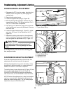
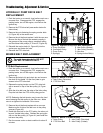
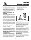
Gauge Wheels
The mower gauge wheels can be placed in two posi-
tions depending on the height of cut. When using higher
cutting heights, set the wheels in the lower position.
When using lower cutting heights, set the wheels in the
upper position. To adjust:
1. Remove the hair pin clip (A, B, Figure 37).
2. For upper position, install the pin (A) through the
spindle above the bracket (C). For the lower posi-
tion, push down on the top of the spindle, and install
the hair pin clip (B) below the top of the bracket (C).
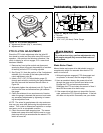
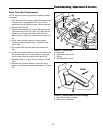
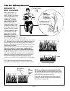
Cutting Height Adjustment
The cutting height adjustment pin (A, Figure 38) controls
the mower cutting height. The cutting height is
adjustable between 1-3/4” (4.4cm) and 5” (12.7cm) in
1/4” (.64cm) increments.
Depress the deck lift foot pedal (B, Figure 38), placing
the majority of the force on the top edge of the pedal
until it locks into the “TRANSPORT” position. Place the
cutting height adjustment pin in the desired cutting
height. Depress the deck lift foot pedal, placing the
majority of the force on the bottom edge of the pedal to
release the pedal from the “TRANSPORT” position.
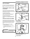
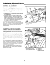
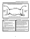
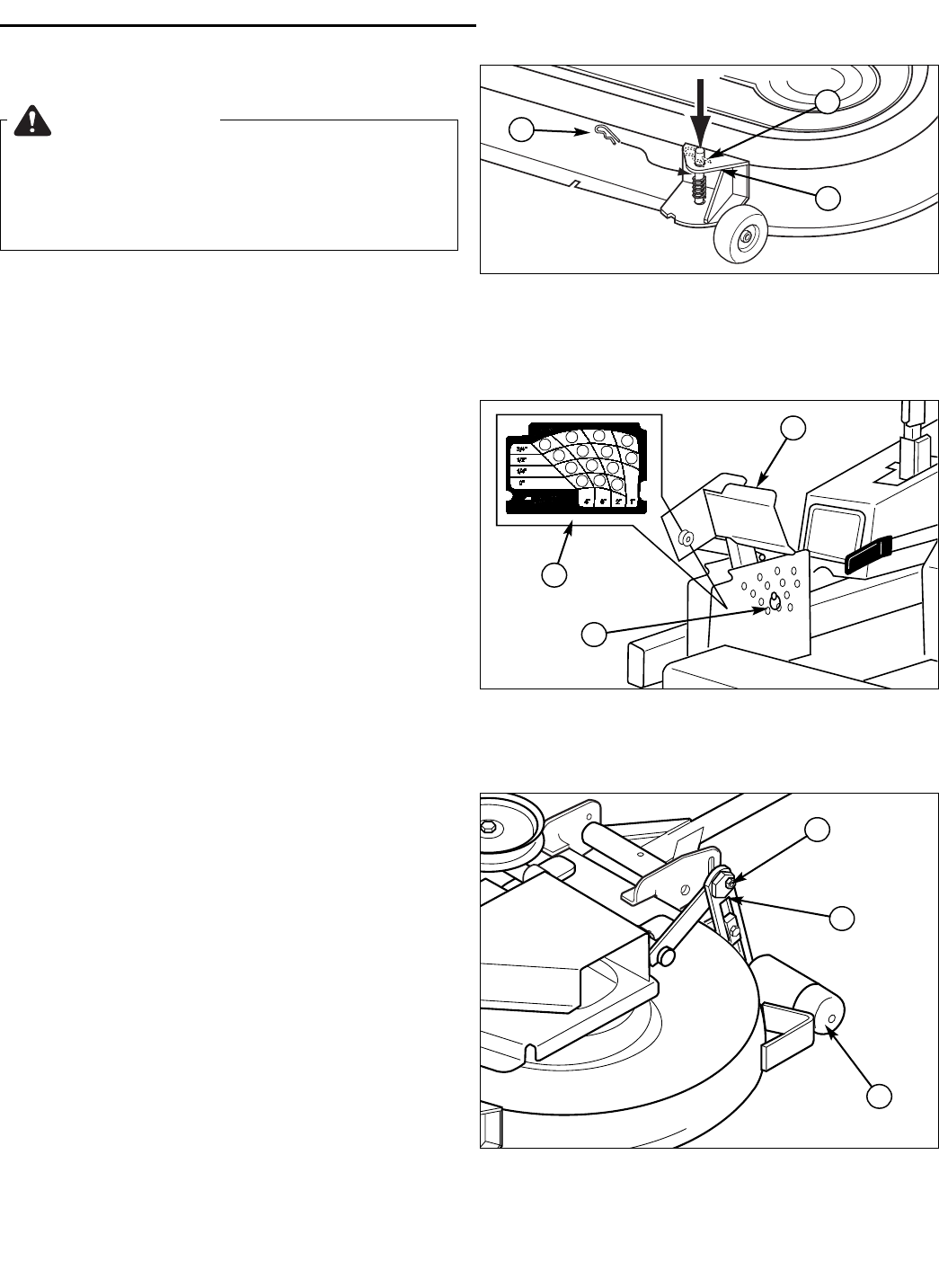
Deck Roller Adjustment
Level the roller, side-to-side using the eccentric nuts.
First place the cutting height adjustment in the 1-3/4”
position. See figure 39. Loosen the outside nut (C)
then turn the eccentric nut (B) to raise or lower the roller
bar. There should be approximately 1/4” of ground
clearance in the lowest cutting position. This clearance
will increase as the height of cut increases.
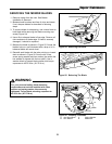
WARNING
Before checking mower, shut off PTO and engine.
Allow all moving parts to stop. Remove ignition
key, then disconnect the spark plug wire and
fasten it away from the spark plug.
A
C
B
Figure 37. Gauge Wheel Adjustment
A. Hair Pin (Upper Position)
B. Hair Pin (Lower Position)
C. Gauge Wheel Bracket
A
B
C
Figure 38. Cutting Height Adjustment
A. Cutting Height Adjustment Pin
B. Deck Lift Foot Pedal
C. Cutting Height Selection Decal
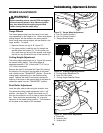
Figure 39. Deck Roller Adjustment
A. Roller Bar
B. Eccentric Nut
C. Outside Nut
C
A
B
29