


12
Operating the Zero Turn Rider
MOWER DECK REMOVAL &
INSTALLATION
Removing the Mower Deck
NOTE: Perform mower removal on a hard, level surface
such as a concrete floor.
1. Push the deck lift pedal forward until it locks in the
“TRANSPORT” position and remove the height
adjustment pin.
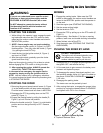
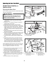
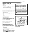
2. Place two, 2” x 4” blocks (B, Figure 10) under the
outside edges of the mower.
3. Release the deck lift pedal to lower the deck.
4. Dismount the mower and push back on the deck lift
pedal until the mower chains are slack. Reinstall the
height adjustment pin in any hole to prevent the
pedal from pivoting forward and applying tension to
the chains.
5. Remove the hairpin clip and clevis pin and remove
the deck lift foot pedal.
6. Remove the hairpin clip, push down on the top of the
spindle, and rotate the gauge wheel (A, Figure 10)
into sliding position. Replace the hair pin clip.
7. Lift the floor plate to gain access to the deck drive
belt.
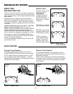
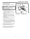
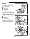
8. Release the spring tension on the deck drive belt
with a wrench on top of the idler pulley (A, Figure
11). Slide the drive belt over the edge of the idler
pulley to remove the belt. Remove the belt from the
PTO clutch pulley groove before proceeding.
NOTE: Releasing the belt tension may loosen the hard-
ware fastening the idler pulley to the idler arm. Make
sure to re-tighten the hardware if this occurs.
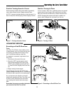
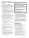
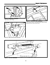
9. Remove the chain mounting hardware from the lift
arm end of the chain (B, Figure 12).
10. Remove the hardware fastening the roller position
link (D, Figure 12) from the pusher bar end.
11. Remove the 2” x 4” blocks from under the mower.
12. Remove the rear deck mount pins (C, Figure 12) and
let the pusher bar (A, Figure 12) swing out of the
way.
13. Slide the mower out from under tractor.
WARNING
Engage parking brake, disengage PTO, stop
engine and remove key before attempting to
install or remove the mower.
Figure 10. Gauge Wheels
A. Gauge Wheel
B. 2” x 4” Block
Figure 12. Rear Deck Mount (right side shown)
A. Pusher Bar(s) C. Bar Mount Pin(s)
B. Chain Mount Hardware D. Roller Position Link
(all locations) (right side only)
D
A
B
C
Figure 11. Mower PTO Belt
A. Idler Pulley (Flat-sided)
B. PTO Drive Belt
B
A
A
B