


Troubleshooting, Adjustment & Service
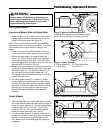
BRAKE PAD REPLACEMENT
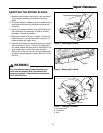
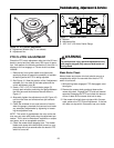
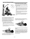
1. Remove the adjuster bolt (I, Figure 14) from the
brake caliper housing (A, Figure 14), disconnect the
clevis pin from the brake lever (C, Figure 14) and
remove the bolts holding the brake mount to the
engine deck.
2. Remove the brake caliper assembly from the mount,
remove the two housing bolts (G, Figure 14) and
separate the caliper halves.
3. Remove the brake pad (F, Figure 14) and backing
plate (E, Figure 14) and discard worn brake pad.
4. Remove the actuator pin (D, Figure 14) and inspect
the pin and brake lever (C, Figure 14) for galling or
cracks. If either is defective, these parts should be
replaced in sets.
5. Grease the spherical end of the actuator pin, the
spherical end of the adjuster bolt and the ramp areas
of the brake lever with a good TEFLON-additive
grease. Replace the actuator pin into the caliper
housing, spherical end first. Replace the adjuster
bolt only by a few threads to hold it in place.
6. Place the back plate into the brake caliper housing,
then the new brake puck on top of the back plate.
7. If the brakes are severely worn, it may be necessary
to replace the anvil side (B, Figure 14) of the brake
caliper.
8. Reassemble the brake caliper and tighten the hous-
ing bolts to 24 ft.lbs. (32 N.m.).
9. Replace the caliper in the brake mount, reassemble
the brake mount to the engine deck, reconnect the
clevis to the brake lever.
10. See STEERING BRAKE ADJUSTMENT for proper
adjustment.
21