


62
TP 400-2307-03-LW-S
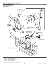
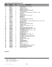
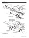
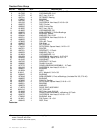
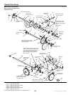
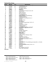
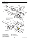
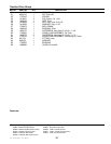
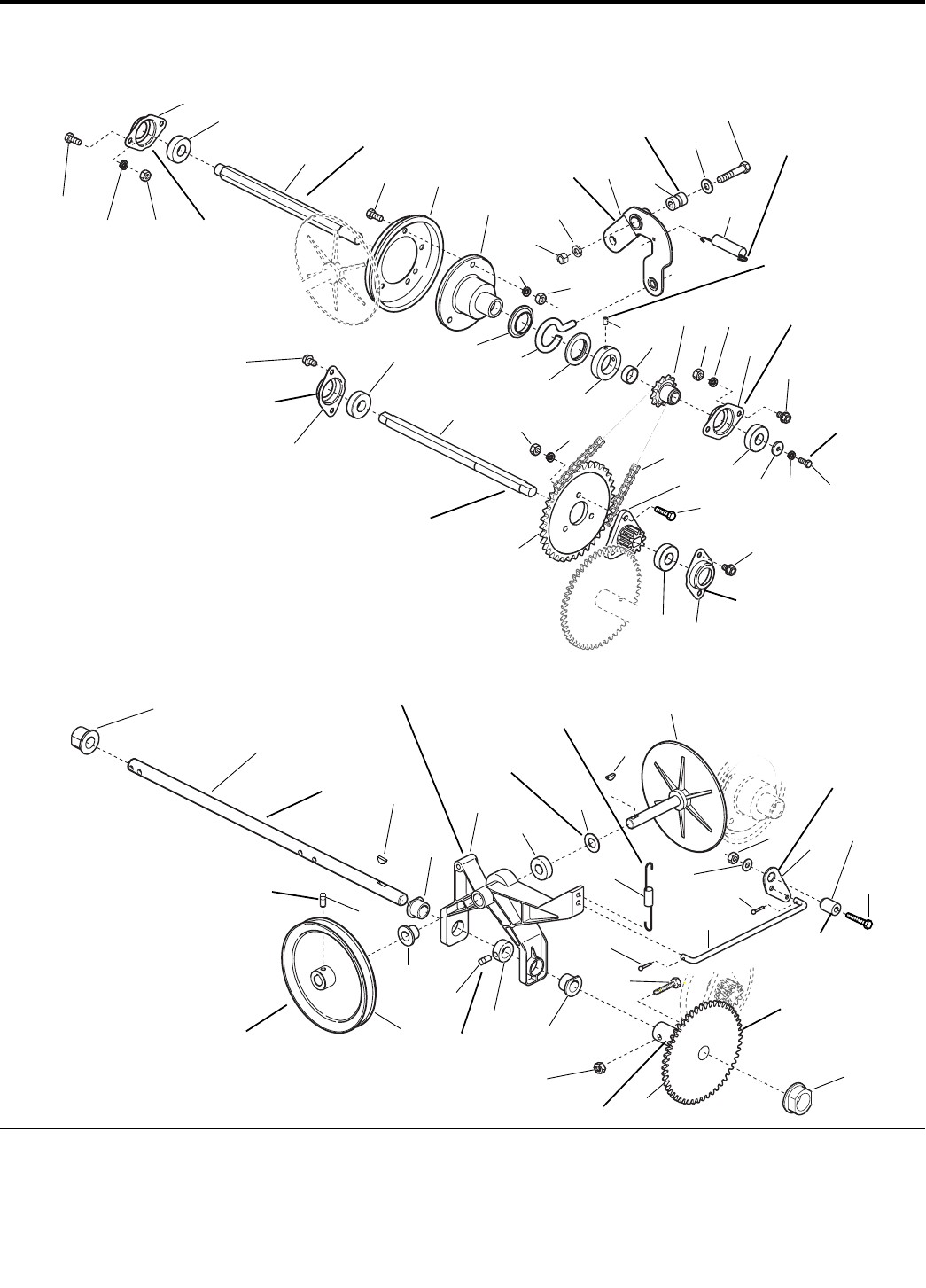
Traction Drive Group
NOTE: Unless noted otherwise,
use the standard hardware torque
specification chart.
985772
The above parts group applies to the following Mfg. Nos.:
1693763 860M, 8HP Manual Start
1693775 860M, 8HP Manual Start (Export)
1693984 860M, 8HP Manual Start
1693985 860M, 8HP Manual Start (Export)
1694242 860E, 8HP Electric Start
© Copyright 2002 Simplicity Manufacturing, Inc. All Rights Reserved.
Mounted outside
of frame.
Mounted outside
of frame.
Mount to bracket in
frame weldment.
Pack groove
with grease.
Hook end to top left
corner slot of frame.
Apply locktite, torque
to 55 - 60 in-lbs. when
all parts are tight against
hub.
Mounted inside
of frame.
Apply locktite,
torque to
8 - 10 ft-lbs.
Be sure tie bar support is in place. Move
axle to left (as viewed from back) to take
up end play. Move set collar (Ref. 43) to
right to remove end play in pivot arm
(Ref. 36). Torque set screw (Ref. 39)
to 10 - 14 ft-lbs.
Mounted outside
of frame.
Hook upper end
into hole of frame top.
Flat side towards
bearing.
Torque to
18 - 21 ft-lbs.
Assemble items 38, 36 &
42 with no end play. Parts
must rotate freely.
Apply anti-seize compound to
wheel hub area of Ref. 33 & 45.
Must pivot
freely.
Mount in hole at
upper rear corner
of frame.
Grease bearing
area of Ref. 45.
Lubricate with
5W 50 Synthetic oil.
Mounted inside of frame.
Apply grease to
bearing areas.
Torque to
10 - 14 ft-lbs.
Apply thread locking solution,
let cure for 8 hours and check
torque to 20 ft-lbs.
1
2 3
4
5
6
7
8
9
10
11
12
13
14
15
16
17
18
19
20
21
22
23
24
25
26
27
28
29
30
31
32
33
34
35
36
37
38
39
40
41
42
43
44
45
46
47
48
49
50
51
52
53
54
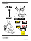
35
44
48
5
3
2
17
1
4
2
3
5
4
26
5
2
3
4
39
34