


20
www.simplicitymfg.com | www.snapper.com
OPERATION
MOWER REMOVAL AND
INSTALLATION
NOTE: Perform mower installation and removal on a
hard flat surface such as a concrete floor.
Removal
1. Disengage the PTO, engage the parking brake,
turn off the ignition, remove the key, and wait for
all moving parts to stop.
2. Remove the cutting height pin and lower the
attachment lift to its lowest position.
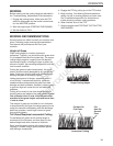
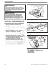
3. Pull the lever (A, Figure 10) towards the rear of
the machine to release tension on the mower
belt. Secure the lever in the guard notch (B), if
equipped. Remove the mower belt from the PTO
pulley (C, Figure 9).
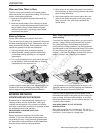
4. Pull the hair pins (C & D, Figure 11) and
disconnect the deck leveling links (I & J). Pull the
hair pin and disconnect the roller bar connecting
rod (M), if equipped. Pull and turn the rod locks
(A, B, E & F) to release the rod ends.
5. Lift to front of the deck using a 2 x 4 as a lever, pull
the handle (G) forward to release the front hangers
rod ends (H), then push rearward to release the
rear rod ends.
6. Pivot the front wheels out of the way and slide the
mower deck out from under right side of the unit.
Installation
1. Disengage the PTO, engage the parking brake,
turn off the ignition, remove the key, and wait for
all moving parts to stop.
2. Remove the cutting height pin and lower the
attachment lift to its lowest position.
3. Pivot the front wheels out of the way and slide the
mower under the unit.
4. Install the leveling links and hair pins (I, J, C & D)
5. Lift the rear of the mower and install the rear lift
rods (K & L) and secure with the rear rod locks (E
& F).
6. Install the roller bar connecting rod and hair pin
(M), if equipped.
7. Lift to front of the deck using a 2 x 4 as a lever,
pull the handle (G) to align the front hanger rod
ends (H) with the slots and secure with the front
rod locks (A & B).
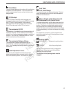
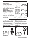
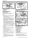
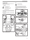
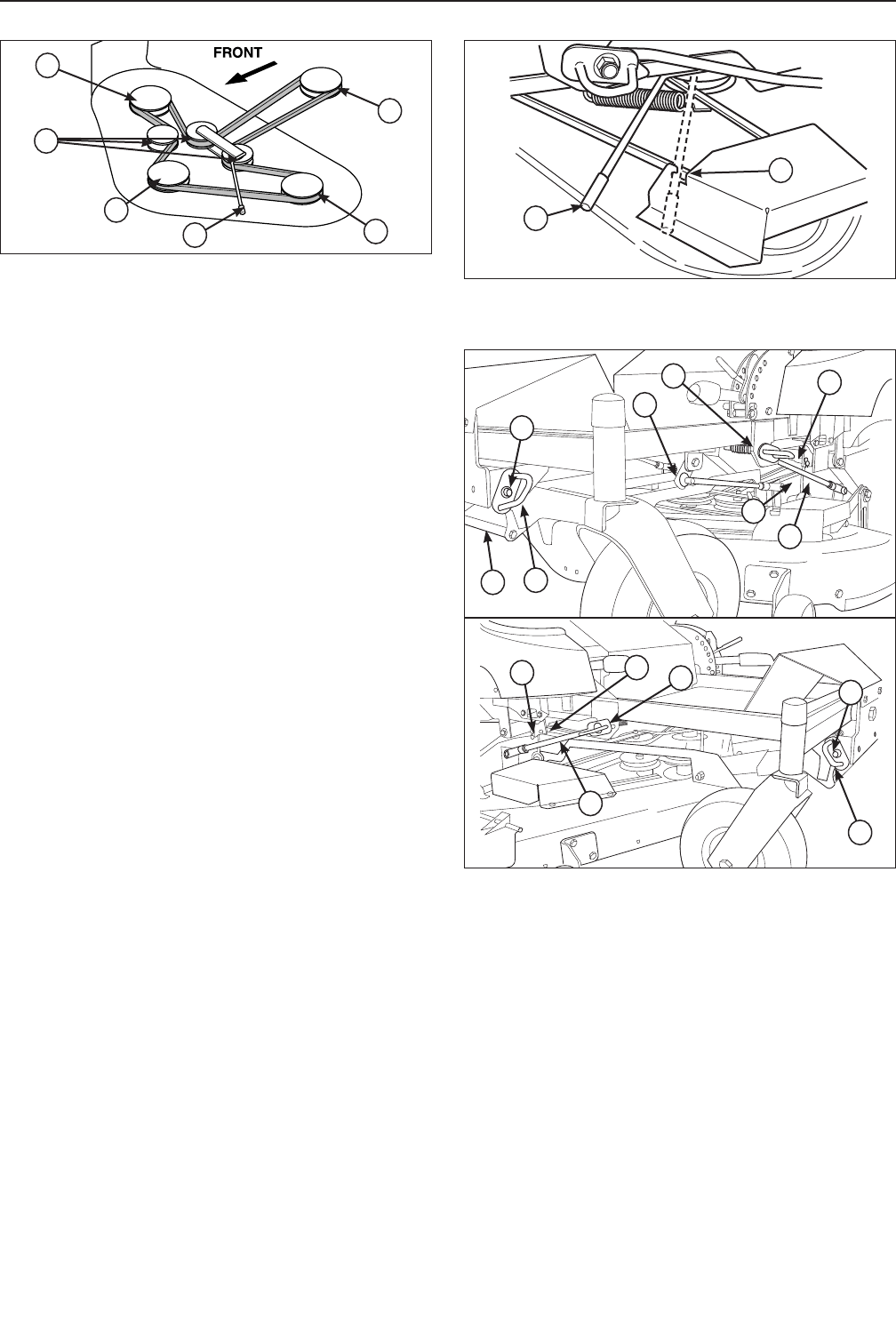
Figure 9. Mower Belt Routing
A. Arbor Pulleys
B. Back-Side Idlers
C. PTO Pulley
D. Belt Tension Release Lever
A
A
A
C
D
B
8. Install the belt as shown in Figure 9.
9. Release tension from the tensioning idler pulley
using the belt tension lever (A, Figure 10) and
make sure the belt is seated properly in all pulleys.
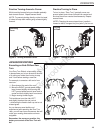
Figure 10. Release Belt Tension
A. Belt Tension Release Lever
B. Guard Notch (44” & 50” Models Only)
A
B
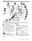
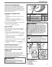
Figure 11. Mower Installation & Removal
A. Left Front Rod Lock
B. Right Front Rod Lock
C. Left Leveling Link Hair Pin
D. Right Leveling Link Hair Pin
E. Left Rear Rod Lock
F. Right Rear Rod Lock
G. Handle
H. Front Hanger Rod Ends
I. Left Leveling Link
J. Right Leveling Link
K. Left Rear Lift Rod
L. Right Rear Lift Rod
M. Roller Bar Connecting Rod (44” & 50” Models)
B
A
E
F
J
C
D
L
H
G
H
I
K
M
Not for
Reproduction