


30
Troubleshooting, Adjustments, & Service
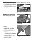
TRANSMISSION DRIVE BELT
REPLACEMENT
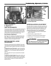
1. Park the rider on a smooth, level surface such as a
concrete floor. Disengage the PTO, lock the motion
control levers into their neutral locked positions, turn
off the engine, and remove the ignition key.
2. Remove the mower belt from the PTO pulley (see
MOWER BELT REPLACEMENT for instructions).
3. Relieve tension on the transmission belt (A, Figure
33a) by moving the idler arm (E) in the direction indi-
cated by the curved arrow, and remove the old belt
from the crankshaft and transmission pulleys.
4. Loosen (do not remove) the anti-rotation bracket
hardware (C, Figure 33a), and slip the old belt out
between the anti-rotation pin (B) and the PTO (A).
Note: The PTO wiring harness must be disconnected
from the main wiring harness in order to remove and
replace the transmission belt. Be sure to reconnect the
harness after the belt is replaced.
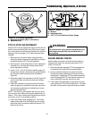
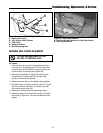
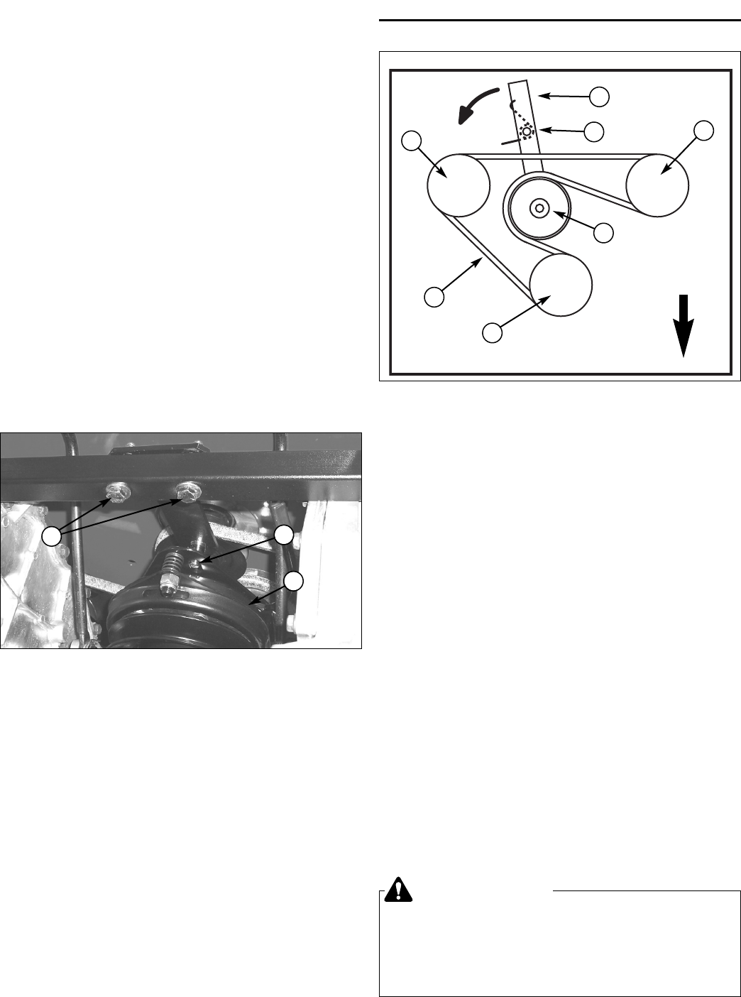
Figure 33b. Transmission Drive Belt Replacement
(Shown from Below; Components Removed for
Clarity)
A. Transmission Drive Belt
B. Crankshaft Pulley
C. Transmission Pulley (2)
D. Idler Pulley
E. Idler Arm
F. Idler Tension Spring
F
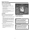
BATTERY CHARGING
A dead battery or one too weak to start the engine may
be the result of a defect in the charging system or other
electrical component. If there is any doubt about the
cause of the problem, see your dealer. If you need to
replace the battery, follow the steps under Cleaning the
Battery & Cables in the Regular Maintenance Section.
To charge the battery, follow the instructions provided by
the battery charger manufacturer as well as all warnings
included in the safety rules sections of this book.
WARNING
Keep open flames and sparks away from the
battery; the gasses coming from it are highly
explosive.Ventilate the battery well during
charging.
C
D
C
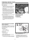
FRONT
B
A
E
Remove the battery from the rider and place on a level,
non-concrete surface. Charge the battery at 6-10 amps
for 1 hour. Do not charge at a rate higher than 10 amps.
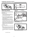
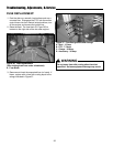
Figure 33a. Anti-Rotation Bracket
(View Looking Back from Mower Deck)
A. PTO Clutch
B. Anti-Rotation Pin
C. Anti-Rotation Bracket Hardware
A
B
C
5. Reversing steps 3-4, install the new belt, following the
routing in Figure 33b. Make sure the V-side of the
belt runs in the grooves of the crankshaft pulley and
transmission pulleys (B & C). Also, make sure that
the anti-rotation pin (B, Figure 33a) is inserted into
the anti-rotation slot on the PTO before tightening
hardware (C).
6. Reinstall the PTO drive belt.